2-10 EdgeFLEX 600 - Release 2.0
EdgeFLEX 600 Installation
Connecting System Cables
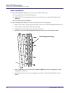
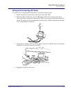
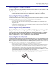
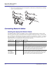
5. When the connector block has been secured as shown below, the circuit breaker switch may be
switched to the ON position to power the EdgeFLEX 600.
Connecting System Cables
System Management Connections
The front panel of the EdgeFLEX 600 provides all the connections for the system cables. For pinouts
of system management connectors, see Appendix A, “Connector Pin Assignments”.
System Management Connectors
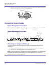
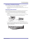
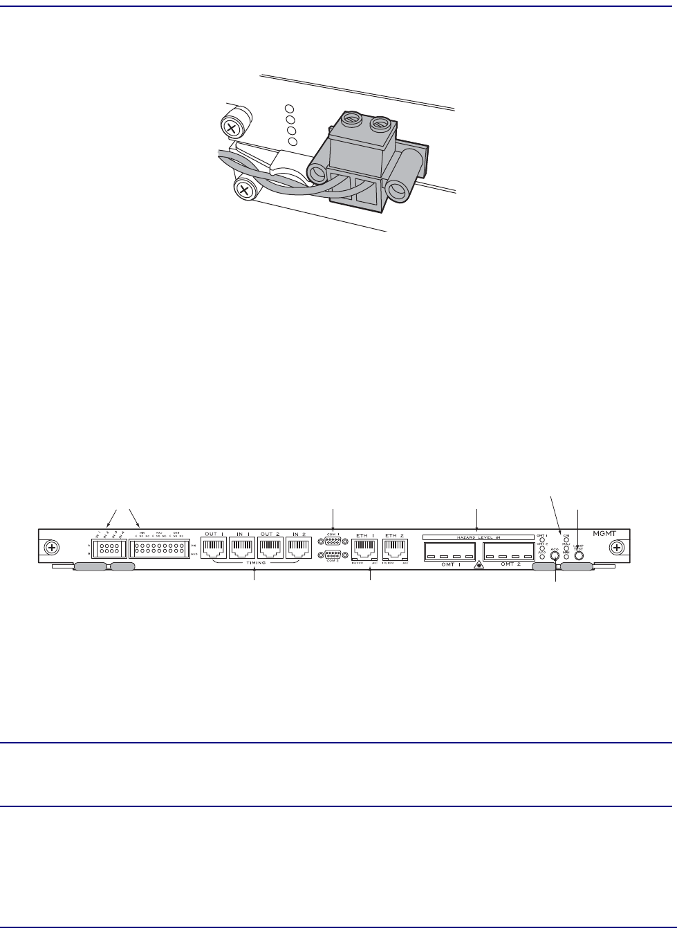
The Management card (MGMT) provides all system management connectors. The following
illustration shows the location of the system management connectors on the MGMT card.
Connecting the Management Cable(s)
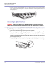
To connect an Ethernet cable to the management connector on the EdgeFLEX 600, perform the
following steps:
1. Locate the 10/100 Ethernet cable to use as the LAN connection for network management.
2. Insert the LAN cable RJ-45 connector into the port labeled ETH 1.
NOTE: If you are configuring a redundant LAN connection, repeat steps 1 and 2 and connect
the second LAN cable to the port labeled ETH 2. Note: use of both ETH 1 and ETH 2
simultaneously is not currently supported.)
Management Ethernet Ports 1 & 2
Alarm Relay Contact Blocks
OMT Receptacles 1 & 2
Alarm Cutoff Button
Lamp Test Button
System Alarm LEDs
RS-232 Serial Management Ports 1 & 2
Timing Inputs and Outputs


