EdgeFLEX 600 - Release 2.0 2-13
EdgeFLEX 600 Installation
Connecting Network Cables
Connecting to 10/100 Ethernet Interfaces
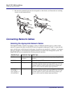
To connect 10/100 Ethernet network cables to the EdgeFLEX 600, perform the following steps:
1. At the front of the chassis, locate the 10/100 Ethernet cable(s) to install.
2. Insert the RJ-45 cable connector into the appropriate 10/100 Ethernet interface connector on an
Ethernet card.
Connecting to DS1/E1 Interfaces
The EdgeFLEX 600 DS1/E1 interface cards use a special high-density connector and octopus cable
connect to a sixteen port breakout-panel that provides standard RJ-style physical interfaces.
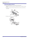
To connect the DS1/E1 POD to the DS1/E1 breakout panel, perform the following steps:
1. At the front of the chassis, locate the high-density connector on the DS1/E1 POD to be
connected.
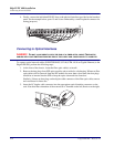
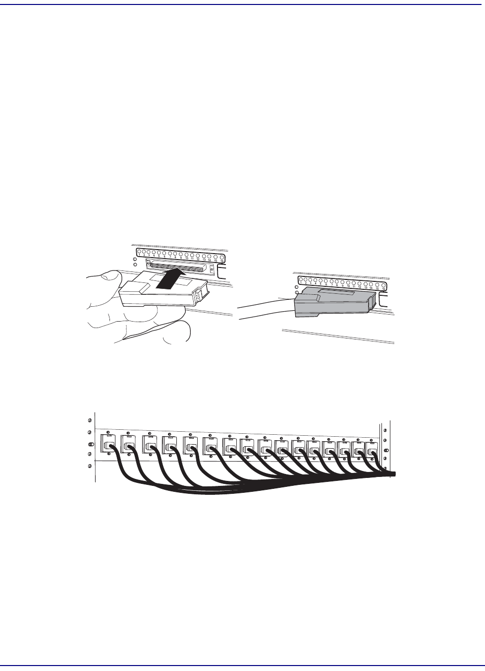
2. Insert the high-density plug on the octopus cable into the high-density connector on the DS1/
E1 card as shown below. The connector will snap into place if seated correctly.
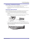
3. Connect the sixteen DS1/E1 connectors on the octopus cable to the sixteen DS1/E1 RJ-48
connectors into the back of the DS1/E1 breakout panel, as shown below. Each connector on the
breakout cable is tagged with its port number; be sure to plug the correct connector into each
receptacle on the breakout panel.


