


A-2 EdgeFLEX 600 - Release 2.0
Connector Pin Assignments
Pin Locations
Pin Locations
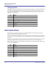
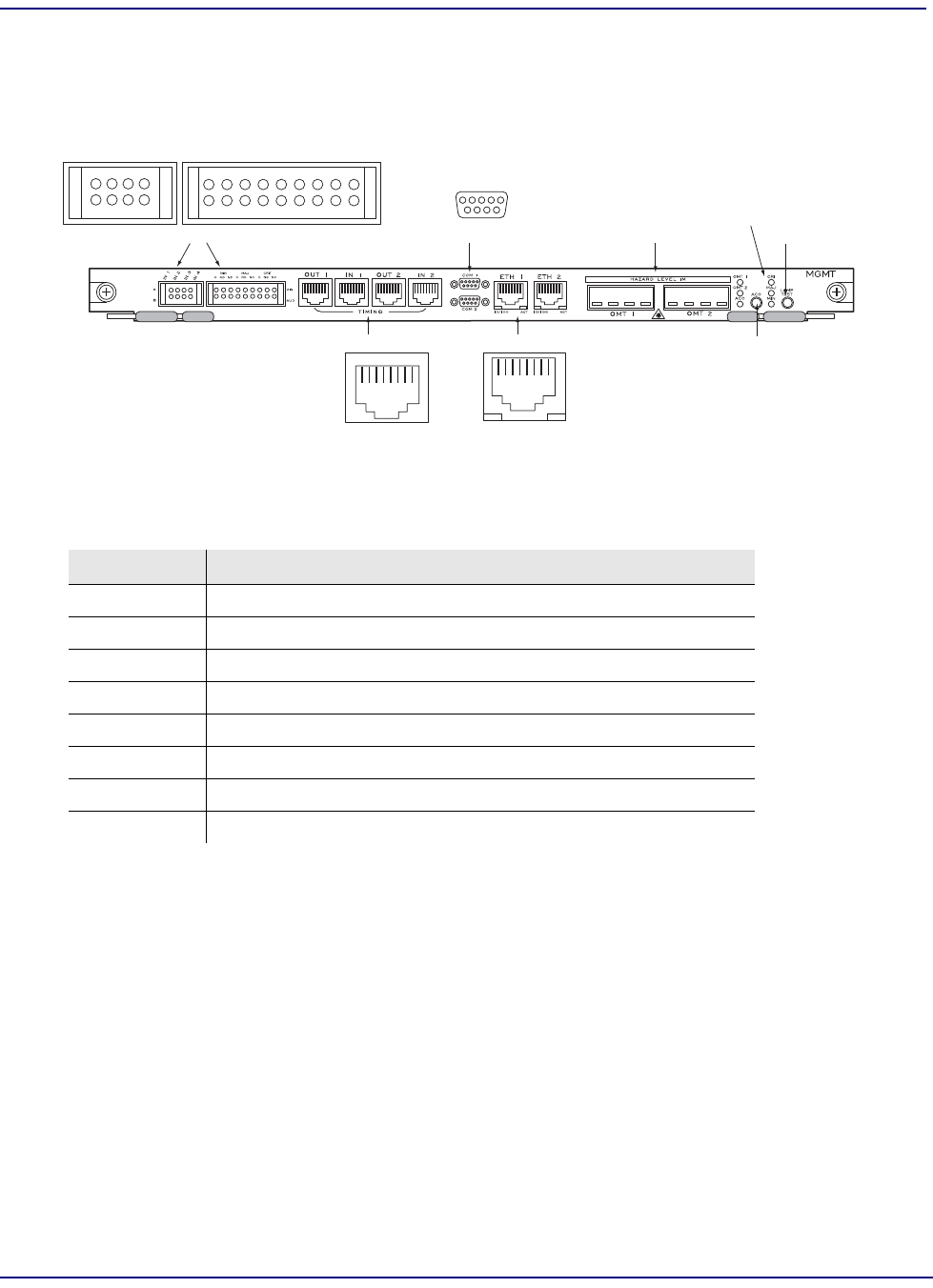
The tables in this appendix list the connector pin assignments for the ports on the Management card.
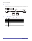
The following illustration provides pinout numbering arrangements for reference.
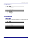
Ethernet (RJ-45) Pinout (management port)
Pin Signal
1 TD+ (Transmit to UTP)
2 TD- (Transmit to UTP)
3 RD+ (Receive from UTP)
4 Not used
5 Not used
6 RD- (Receive from UTP)
7 Not used
8 Not used
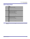
Management Ethernet Ports 1 & 2
Alarm Relay Contact Blocks
OMT Receptacles 1 & 2
Alarm Cutoff Button
Lamp Test Button
System Alarm LEDs
RS-232 Serial Management Ports 1 & 2
Timing Inputs and Outputs
1
2
7
18
18
8
1
2
15
69
17
18