


20020601
English
Activity: SetupActivity: Setup
2-9-1
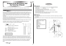
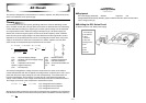
í Equipment
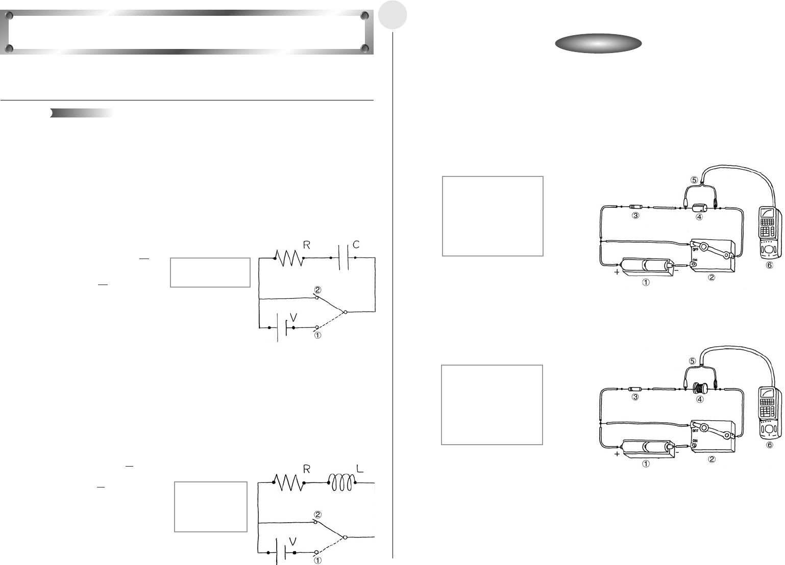
Battery (D.C. Power Supply) Resistor Capacitor Coil Switch
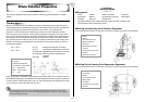
Voltage Measurement Setup (EA-200, graphic scientific calculator, data communication
cable, voltage probe)
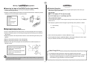
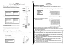
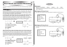
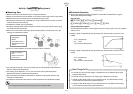
í Building the RC Series Circuit
u The product of the resistance value and the capacitor’s capacitance should be around 1.
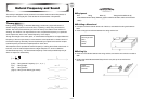
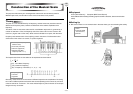
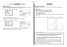
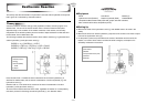
í Building the RL Series Circuit
u The quotient when the resistance value is divided by the self-inductance of the coil should
be around 1.
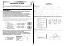
This activity investigates transient phenomena when direct current flows through a capacitor
and coil.
Generally speaking, electrical current is the movement of free electrons within metal. When
electrical current flows through a capacitor, electrons are accumulated, and the capacitor
stores the charge. The accumulation of an electrical charge is called “charging,” while the
loss of the charge by the capacitor is called “discharging.”
Connecting a resistor and capacitor serial circuit to a D.C. power supply causes current to
flow to the capacitor, which charges until it reaches a steady state. Now if the power supply
is removed and the circuit is closed, current flows to the capacitor again, which now
discharges until it reaches a steady state. Current flows to the capacitor in the opposite
direction that it flowed during charging. The change in capacitor voltage during the transient
phase until the capacitor reaches a steady state, while charging and discharging is
represented by the expression shown below.
V
R(V): Voltage Across the Resistor
V
C(V): Voltage Across the Capacitor
V(V) : Power Supply Voltage
R(Ω) : Resistance
C(F) : Capacitance
t(s) : Time
When the current flowing through a coil changes over time, the coil induces voltage, like an
electrical generator. This is called “self-induced electromotive force,” which acts to oppose
the change in current. When a D.C. power supply is connected in a resistor and coil series
circuit, the effect of the coil’s self-induced electromotive force can be observed until current
reaches a fixed value. Similarly, self-induced electromotive force can also be observed by
cutting off the power supply to a circuit through which steady current is flowing.
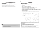
The change in coil voltage during these transient phases is represented by the expressions
below.
V
R(V): Voltage Across the Resistor
V
L(V): Voltage Across the Coil
V(V) : Power Supply Voltage
R(Ω) : Resistance
L(H) : Self-inductance
t(s) : Time
Direct Current and Transient Phenomena
Theory
1 3V D.C. Power Supply
2 Switch
3 10kΩ Resistor
4 100
µ
F Capacitor
5 Voltage Probe (CH1)
6 EA-200
1 3V D.C. Power Supply
2 Switch
3 0.1Ω Resistor
4 100mH Coil
5 Voltage Probe (CH1)
6 EA-200
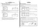
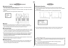
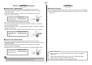
1 Circuit With
Power Supply
2 Circuit Without
Power Supply
VC = V – VR = V 1– e
V
C = VR = V
e
t
RC
–
t
RC
–
( )
VL = VR – V = – V
e
VL = VR = V
e
R
L
–
t
R
L
–
t
1 Charge Circuit
2 Discharge Circuit