


1-21
Cisco 12006 and Cisco 12406 Router Installation and Configuration Guide
OL-11497-03
Chapter 1 Product Overview
Route Processors
Flash memory also functions as a Trivial File Transfer Protocol (TFTP) server to
allow other servers to boot remotely from stored images or to copy them into their
own Flash memory. The onboard Flash memory (called bootflash) contains the
Cisco IOS boot image, and the Flash memory card contains the Cisco IOS
software image. To order a spare Flash memory card, use Cisco product number
MEM-GRP-FL20=, which is a 20-MB Type II PCMCIA Flash memory card.
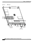
System Status LEDs
The GRP faceplate contains two types of system status LEDs: alphanumeric LED
displays and device or port activity indicators.
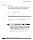
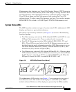
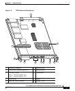
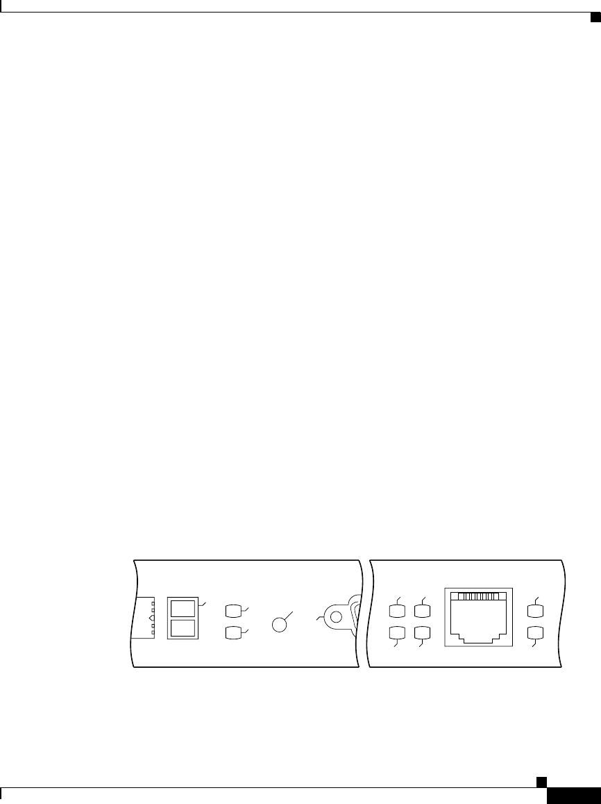
The device or port activity indicators (see Figure 1-6) consist of the following
functional groups:
• Two Flash memory card activity LEDs (labeled SLOT-0 and SLOT-1)—one
LED per Flash memory slot—Turns on when the slot is accessed.
• Four RJ-45 Ethernet port activity LEDs (labeled LINK, COLL, TX, and
RX)—These LEDs are used only by the RJ-45 Ethernet connector and are
disabled when the media-independent interface (MII) Ethernet port is in use.
The LEDs indicate link activity (LINK), collision detection (COLL), data
transmission (TX), and data reception (RX).
• Two Ethernet port selection LEDs (labeled MII and RJ-45)—When on, these
LEDs identify which one of the two Ethernet connections you selected. When
the RJ-45 port is selected, its LED is on and the MII LED is off. When the
MII port is selected, its LED is on and the RJ-45 LED is off.
Figure 1-6 GRP LEDs (Partial Front Panel)
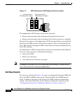
The alphanumeric LED displays (see Figure 1-7) are organized as two rows of
four characters each. The content of the displays is controlled by the MBus
module software. Both rows of the display are powered by the MBus module.
57075
SLOT-0
SLOT-1
COLL
LINK
TX
RX
RJ-45
MII
RESET
AUX
EJECT