


1-7
Cisco 12006 and Cisco 12406 Router Installation and Configuration Guide
OL-11497-03
Chapter 1 Product Overview
Physical and Functional Description
Physical and Functional Description
The main physical components of Cisco 12006 and Cisco 12406 routers and their
functions are described in the following sections:
• Chassis, page 1-7
• Multigigabit Crossbar Switch Fabric, page 1-10
• Maintenance Bus, page 1-13
• Route Processors, page 1-15
• Line Cards, page 1-33
• Alarm Cards, page 1-35
• Power Subsystems, page 1-37
• Blower Module, page 1-47
• Air Filters, page 1-49
• Cable-Management System, page 1-50
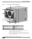
Chassis
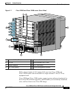
The Cisco 12006 and Cisco 12406 router chassis is an enclosure that consists of
two integral card cages and two power module bays. (see Figure 1-1.)
RP and Line Card Slots
The RP and line card cage has six user-configurable slots that support one RP and
up to five line cards. Network interfaces reside on the line cards that connect the
switch fabric of the router to the external networks. For more information about
the role of the RP, see the “Route Processors” section on page 1-15. For more
information about the role of the line cards, see the “Line Cards” section on
page 1-33.
Note Cisco 12006 and Cisco 12406 routers use line cards that are compatible with
other Cisco 12000 series routers.