


1-43
Cisco 12006 and Cisco 12406 Router Installation and Configuration Guide
OL-11497-03
Chapter 1 Product Overview
Power Subsystems
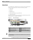
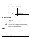
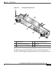
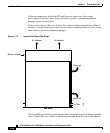
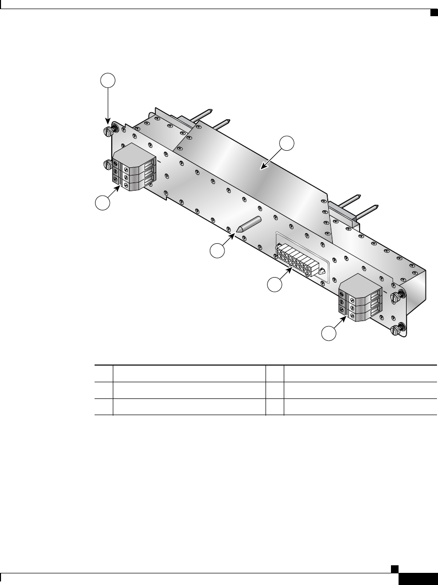
Figure 1-14 DC Power Distribution Unit
DC-input power is connected through the DC PDU on the chassis rear panel. The
DC PDU is equipped with two DC power connector blocks. Each DC power
connector block is equipped with three terminal ports. Leads from the DC source
1 Captive screw 4 DC power distribution unit
2 DC power connector block A 5 Guide pin
3 DC power connector block B 6 Blower module connector
57992
1
2
6
5
4
3
POWER B
POWER A
+
GND
+
GND