


1-37
Cisco 12006 and Cisco 12406 Router Installation and Configuration Guide
OL-11497-03
Chapter 1 Product Overview
Power Subsystems
Power Source Monitoring
The alarm card monitors the power modules and signals when there is a condition
outside the normal range of operation. It discloses problems such as the following:
• Power source voltage is not being provided to a component
• A fault exists in the power source or power module
• Output voltage—Voltage monitor signal is outside the allowable range
• Output current—Current monitor signal is outside the allowable range
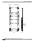
Alarm Relay Contact Connector
The 9-pin D-type alarm relay contact connector on the faceplate of the alarm card
(see Figure 1-11) is used to connect external alarm indication equipment to the
router so that alarm indicator signals in the router can be repeated elsewhere
outside the router.
The pins on this connector are tied directly to the critical, major, and minor alarm
relay contacts (normally open, normally closed, and common). Any event that
causes one of the alarm LEDs on the alarm card faceplate to go on also activates
the corresponding relay contact closure. The relay interface is rated at a maximum
of 2A, 60V, or 50VA, whichever is greater.
Because alarm contact cables are entirely dependent on site-specific
circumstances, alarm connector cables are not available from Cisco. For
information about alarm connector wiring requirements and the pinout for the
alarm connector interface, see the “Alarm Card Alarm Relay Connector
Specifications” section on page A-6.
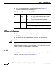
Power Subsystems
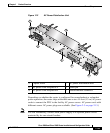
Cisco 12006 and Cisco 12406 routers can be powered by either an AC or DC
power subsystem, as described in the following sections:
• AC Power Subsystem, page 1-38
• DC Power Subsystem, page 1-42
• Power Distribution, page 1-47