


Chapter 1 Product Overview
Chassis
1-8
Cisco 12006 and Cisco 12406 Router Installation and Configuration Guide
OL-11497-03
Switch Fabric Card Slots
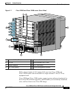
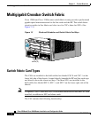
The switch fabric circuitry resides in five fabric card slots: two for CSCs and three
for SFCs. (See Figure 1-1.) For more information about the role of the switch
fabric circuitry, see the “Multigigabit Crossbar Switch Fabric” section on
page 1-10.
Alarm Card Slots
Cisco 12006 and Cisco 12406 routers are equipped with two alarm cards. These
cards are positioned beside one another and occupy two card slots directly under
the CSC slots. (See Figure 1-1.) For more information about the role of the alarm
cards, see the “Alarm Cards” section on page 1-35.
Note The two alarm cards occupy slots under the two CSC slots in the CSC card cage,
but are not part of the switch fabric.
Chassis Backplane
All of the card cages are tied together electrically through a passive system
backplane in the back of the chassis. Nearly all of the wiring and circuitry in the
chassis is contained within or connected to the chassis backplane. The chassis
backplane distributes DC power to all of the cards in the chassis as well as the
blower module, and provides the physical communication pathway between
cards, both for network data and system communication across the internal system
maintenance bus (MBus).