


Chapter 1 Product Overview
Route Processors
1-22
Cisco 12006 and Cisco 12406 Router Installation and Configuration Guide
OL-11497-03
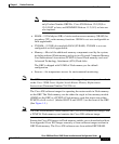
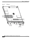
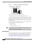
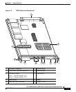
Figure 1-7 GRP Alphanumeric LED Displays (Partial Faceplate)
The alphanumeric LED displays router status messages:
• Router status messages that are displayed during the boot process
• Router status messages that are displayed after the boot process is complete
During the boot process, the alphanumeric LED message displays are controlled
directly by the MBus module. After the boot process, they are controlled by the
Cisco IOS software (through the MBus) and display messages designated by the
Cisco IOS software.
The alphanumeric LED message displays also provide information about different
levels of system operation, including the following:
• Status of the GRP
• Router error messages
• User-defined status and error messages
Note A complete, descriptive list of all system and error messages is located in the
Cisco IOS System Error Messages publications.
Soft Reset Switch
The soft reset switch (see Figure 1-6) causes a nonmaskable interrupt (NMI) and
places the GRP in ROM monitor mode. When the GRP enters ROM monitor
mode, its behavior depends on the setting of the GRP software configuration
register. (For more information on the software configuration register, see the
“Configuring the Software Configuration Register” section on page 4-1.)
Right alphanumeric
LED display (four digits)
Left alphanumeric
LED display (four digits)
57079