


Chapter 1 Product Overview
Power Subsystems
1-44
Cisco 12006 and Cisco 12406 Router Installation and Configuration Guide
OL-11497-03
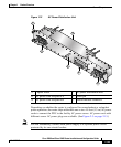
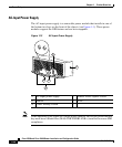
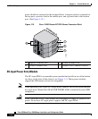
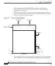
power should be connected to the terminal block. A negative lead is connected to
the top port, a positive lead to the middle port, and a ground lead to the bottom
port. (See Figure 1-15.)
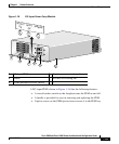
Figure 1-15 Cisco 12006 Router DC PDU Power Connector Block
DC-Input Power Entry Module
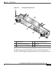
The DC-input PEM is a removable power module that installs in one of the bottom
two bays on the front of the chassis (see Figure 1-1). These power modules
support the OIR feature and are hot-swappable.
Note When operating your router on a single power module, the second power module
bay must have a blank filler (MAS-GSR-PWRBLANK=) installed to ensure EMI
compliance.
Caution Cisco 12006 and Cisco 12406 routers are configured for either AC power or DC
power. Do not mix AC-input power supplies and DC-input PEMs.
1 Negative Terminal Port 3 Ground Terminal Port
2 Positive Terminal Port 4 Terminal Port Connector Screws
57993
POWER A
+
GND
1
4
2
3