


1-47
Cisco 12006 and Cisco 12406 Router Installation and Configuration Guide
OL-11497-03
Chapter 1 Product Overview
Blower Module
Power Distribution
The router chassis backplane distributes -48 VDC power throughout the router
and to all cards in the card cages.
All cards have multiple DC-DC converters that convert the -48 VDC into
+2.5 VDC, +3.3 VDC, +5 VDC, and other voltages as required by the line card.
The DC-DC converters are turned on by the MBus modules under the control of
the RP and MBus software.
Power for the blower module is supplied directly from the backplane through a
connector in the PDU that passes DC voltage from the backplane to the blower
module. An blower module controller card in the blower module converts
–48 VDC into DC voltage that powers the blower module fans.
Caution To ensure that the chassis configuration complies with the required power
budgets, use the on-line power calculator. Failure to properly verify the
configuration may result in an unpredictable state if one of the power units fails.
Contact your local sales representative for assistance.
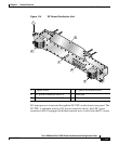
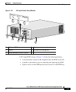
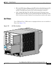
Blower Module
Cisco 12006 and Cisco 12406 routers are equipped with a blower module to
distribute air within the chassis. The blower module is located on the rear of the
chassis. (See Figure 1-2.) The blower module draws room air into the chassis
through two air filters on the side of the chassis, pulls the air through the chassis
card cages, and expels it through exhaust vents on the back of the blower module.
(See Figure 1-17.)
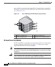
Caution Exhaust from other equipment vented directly into the router air inlet may cause
overheating.
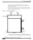
The front, back, and sides of the router must remain unobstructed to ensure
adequate air flow and prevent overheating inside the chassis. Allow sufficient air
flow by maintaining 6 inches (15.24 cm) of clearance at both the inlet and exhaust
openings on the chassis.