


1-31
Cisco 12006 and Cisco 12406 Router Installation and Configuration Guide
OL-11497-03
Chapter 1 Product Overview
Route Processors
At the end of the boot process, the LEDs are controlled by the Cisco IOS software
(via the MBus), and the content displayed is designated by the Cisco IOS
software.
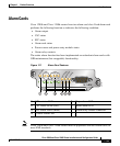
The display LEDs indicate the following information:
• Status of the PRP
• System error messages
• User-defined status and error messages
Note A complete, descriptive list of all system and error messages is located in the
Cisco IOS System Error Messages publications.
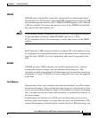
Soft Reset Switch
The soft reset switch causes a nonmaskable interrupt (NMI) and places the PRP
in ROM monitor mode. When the PRP enters ROM monitor mode, its behavior
depends on the setting of the PRP software configuration register. (For more
information on the software configuration register, see the “Configuring the
Software Configuration Register” section on page 4-1. For example, when the
boot field of the software configuration register is set to 0x0 and you press the
NMI switch, the PRP remains at the ROM monitor prompt (
rommon>) and waits for
a user command to boot the system manually. If the boot field is set to 0x1, the
system automatically boots the first IOS image found in the onboard Flash
memory SIMM on the PRP.
Caution The soft reset (NMI) switch is not a mechanism for resetting the PRP and
reloading the IOS image. It is intended for software development use. To prevent
system problems or loss of data, use the soft reset switch only on the advice of
Cisco service personnel.
Access to the soft reset switch is through a small opening in the PRP faceplate. To
press the switch, you must insert a paper clip or similar small pointed object into
the opening.