


Chapter 1 Product Overview
Power Subsystems
1-42
Cisco 12006 and Cisco 12406 Router Installation and Configuration Guide
OL-11497-03
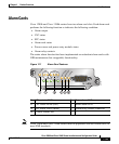
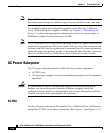
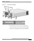
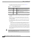
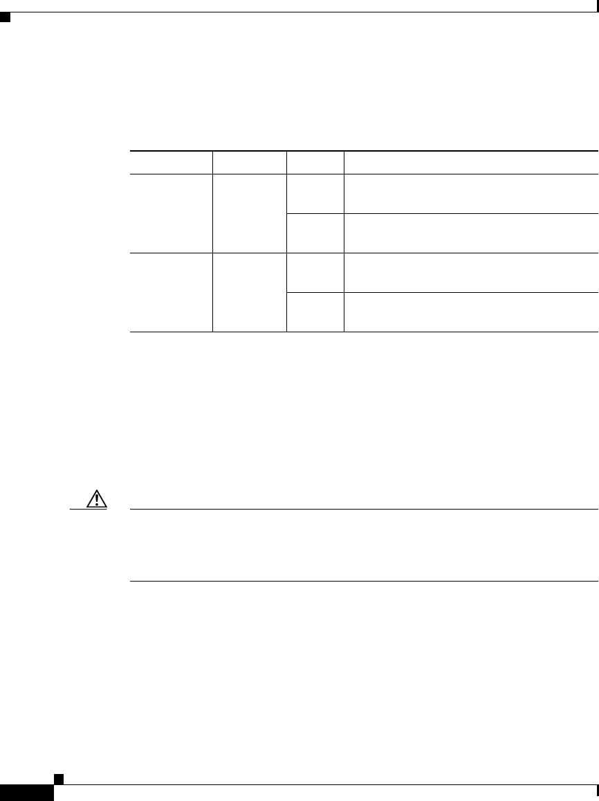
• Two LEDs on the faceplate to provide status information. Table 1-6
summarizes the function of these indicators.
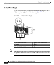
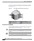
DC Power Subsystem
The DC power subsystem consists of the following system components:
• DC PDU (one)
• DC-input PEMs (one for nonredundant operation; two for redundant
operation)
Caution To ensure that the chassis configuration complies with the required power
budgets, use the on-line power calculator. Failure to properly verify the
configuration may result in an unpredictable state if one of the power units fails.
Contact your local sales representative for assistance.
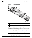
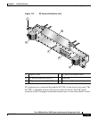
DC PDU
Facility DC power connects to DC-powered routers though the connector blocks
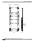
on the DC PDU. (See Figure 1-2 and Figure 1-14.)
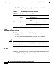
Table 1-6 AC-Input Power Supply LED indicators
LED Label Function State Description
AC Input
power
On AC power source is present and is within
specified limits.
Off Power source is not within specified
limits.
DC Output
Power
On Power supply is operating normally in a
power-on condition.
Off Power supply is operating in a fault
condition and shutdown has occurred.