


12-2
Catalyst 2960 Switch Software Configuration Guide
78-16881-01
Chapter 12 Configuring VLANs
Understanding VLANs
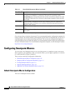
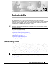
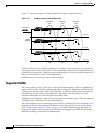
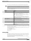
Figure 12-1 shows an example of VLANs segmented into logically defined networks.
Figure 12-1 VLANs as Logically Defined Networks
VLANs are often associated with IP subnetworks. For example, all the end stations in a particular IP
subnet belong to the same VLAN. Interface VLAN membership on the switch is assigned manually on
an interface-by-interface basis. When you assign switch interfaces to VLANs by using this method, it is
known as interface-based, or static, VLAN membership.
Traffic between VLANs must be routed or fallback bridged.
Supported VLANs
The switch supports VLANs in VTP client, server, and transparent modes. VLANs are identified by a
number from 1 to 4094. VLAN IDs 1002 through 1005 are reserved for Token Ring and FDDI VLANs.
VTP only learns normal-range VLANs, with VLAN IDs 1 to 1005; VLAN IDs greater than 1005 are
extended-range VLANs and are not stored in the VLAN database. The switch must be in VTP
transparent mode when you create VLAN IDs from 1006 to 4094.
Although the switch supports a total of 255 (normal range and extended range) VLANs, the number of
configured features affects the use of the switch hardware.
The switch supports per-VLAN spanning-tree plus (PVST+) or rapid PVST+ with a maximum of 128
spanning-tree instances. One spanning-tree instance is allowed per VLAN. See the “Normal-Range
VLAN Configuration Guidelines” section on page 12-5 for more information about the number of
spanning-tree instances and the number of VLANs. The switch supports only IEEE 802.1Q trunking
methods for sending VLAN traffic over Ethernet ports.
Floor 1
Floor 2
Engineering
VLAN
Cisco router
Gigabit
Ethernet
Floor 3
Marketing
VLAN
Accounting
VLAN
90571