


1-3
Catalyst 2960-S Switch Hardware Installation Guide
OL-19732-04
Chapter 1 Product Overview
Front Panel
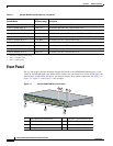
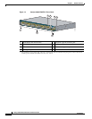
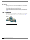
Figure 1-2 Catalyst 2960S-48TS-L Front Panel
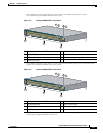
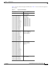
Figure 1-3 Catalyst 2960S-48TS-S Front Panel
1. Port numbering is from left to right, with port 1 on the far left. The first member of the pair (port 1) is above
the second member (port 2). Module slot numbers are 1 and 2.
1 Mode button and switch LEDs 5 USB mini-Type B (console) port
2 10/100/1000 ports
1
1. Port numbering is from left to right, with port 1 on the far left. The first member of the pair (port 1) is above the second
member (port 2). Module slot numbers are 49, 50, 51, and 52.
6 RJ-45 console port
3 SFP module slots 7 Ethernet management port
4 USB Type A port
Catalyst 2960-S
Series
11X
2X
1X
23X
24X
25X
26X
49
51
50
52
47X
48X
POWER
OVER
ETHERNET 740W
37X
39X
36X
38X
11X
14X12X
13X
3
1
2
206694
4
5
6
7
1 Mode button and switch LEDs 5 USB mini-Type B (console) port
2 10/100/1000 ports
1
1. Port numbering is from left to right, with port 1 on the far left. The first member of the pair (port 1) is above the second
member (port 2). Module slot numbers are 49 and 50.
6 RJ-45 console port
3 SFP module slots 7 Ethernet management port
4 USB Type A port
Catalyst 2960-S
Series
SI
11X
2X
1X
23X
24X
25X
26X
49
50
47X
48X
POWER
OVER
ETHERNET 740W
37X
39X
36X
38X
11X
14X12X
13X
206695
3
1
2
4
5
6
7