


1-15
Catalyst 2960-S Switch Hardware Installation Guide
OL-19732-04
Chapter 1 Product Overview
Front Panel
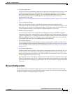
Stack LED
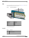
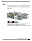
The stack LED shows the sequence of member switches in a stack. Up to four switches can be members
of a stack. The first four port LEDs show the switch member number.
Figure 1-8 shows the LEDs on the
first switch, which is stack member number 1. For example, if you press the Mode button and select
Stack, the port LED 1 blinks green. The LEDs for port 2 and 3 are solid green, as these represent the
member numbers of other stack members. The other port LEDs are off because there are no more
members in the stack.
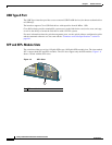
Figure 1-8 Stack LED
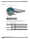
When you select the Stack LED, the respective Stack LEDs are green when the stack ports (on the switch
rear panel) are up, and the respective Stack LEDs are amber when the ports are down. SFP+ module port
LEDs 1 and 2 on the switch show the status for stack ports 1 and 2, respectively.
If the port LEDs are green on all the switches in the stack, the stack is operating at full bandwidth. If any
port LED is not green, the stack is not operating at full bandwidth.
1 Stack member 1 3 Stack member 3
2 Stack member 2
Catalyst 2960XS
Series
PoE 10G
11X
2X
1X
23X
24X
25X
26X
1
2
47X
48X
POWER
OVER
ETHERNET 740W
Catalyst 2960XS
Series
PoE 10G
11X
2X
1X
23X
24X
25X
26X
1
2
47X
48X
POWER
OVER
ETHERNET 740W
Catalyst 2960XS
Series
PoE 10G
11X
2X
1X
23X
24X
25X
26X
1
2
47X
48X
POWER
OVER
ETHERNET 740W
2X
1X
POWER
OVER
ETHERNET 740W
1
2
3
206696