


1-11
Catalyst 2960-S Switch Hardware Installation Guide
OL-19732-04
Chapter 1 Product Overview
Front Panel
LEDs
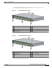
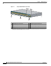
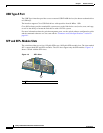
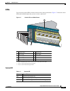
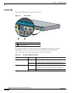
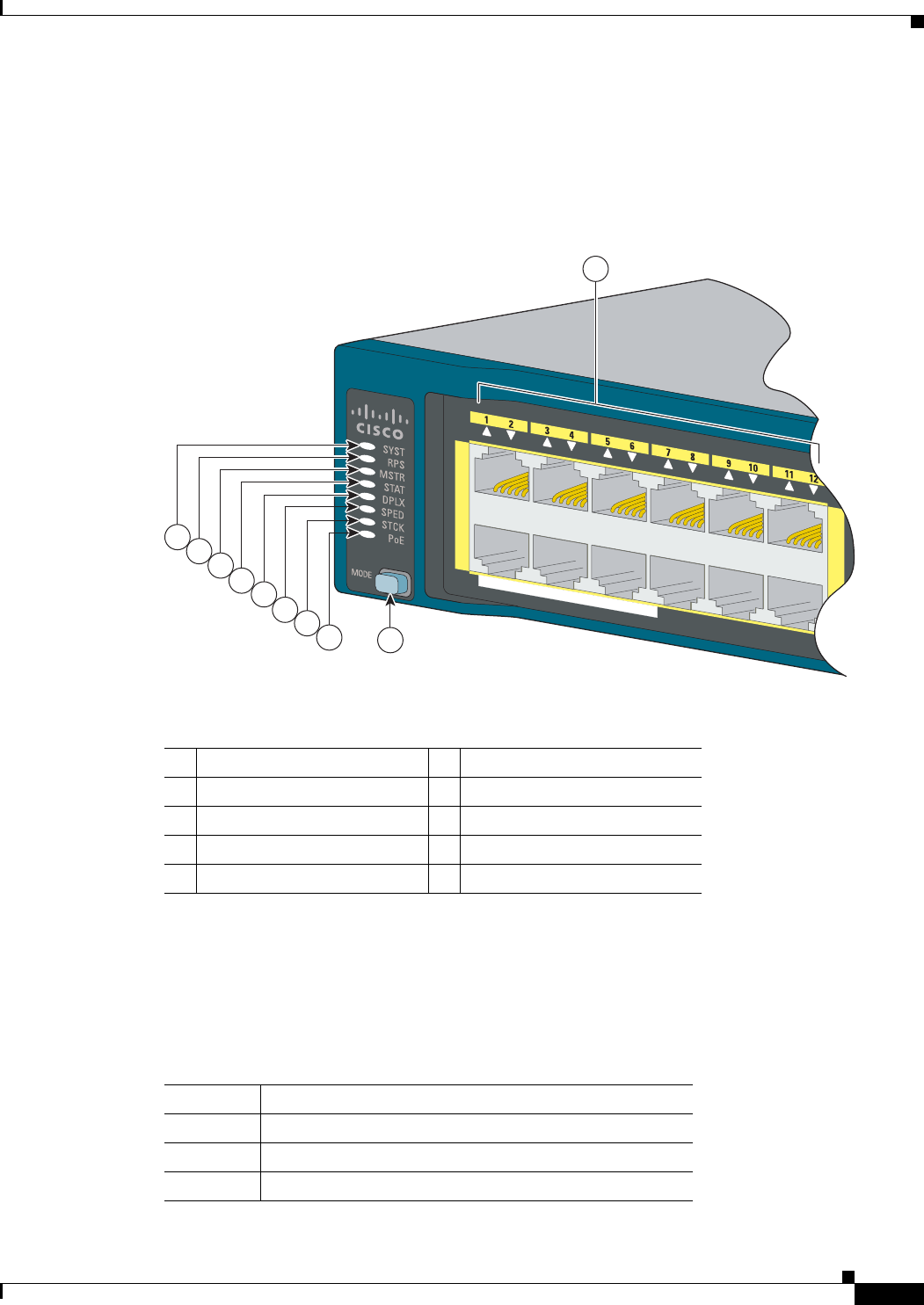
You can use the switch LEDs to monitor switch activity and its performance. Figure 1-7 shows the switch
LEDs and the Mode button that you use to select a port mode.
Figure 1-7 Switch LEDs and Mode Button
System LED
1 System LED 6 Speed LED
2 RPS
1
LED
1. RPS = redundant power system—only on switch models that support RPS.
7 Stack LED
2
2. Only on switch models that support stacking.
3 Master LED
2
8 PoE LED
3
3. Only on switch models that support PoE.
4 Status LED 9 Mode button
5 Duplex LED
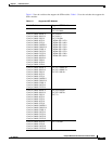
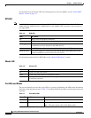
Ta b l e 1-4 System LED
Color System Status
Off System is not powered on.
Green System is operating normally.
Amber System is receiving power but is not functioning properly.
11X
2X
1X
POWER
OVER
ETHERNET 740W
11X
12X
206758
5
6
7
8
4
2
3
1
9
10