


2-25
Catalyst 2960-S Switch Hardware Installation Guide
OL-19732-04
Chapter 2 Switch Installation
10/100 and 10/100/1000 PoE+ Port Connections
Warning
Voltages that present a shock hazard may exist on Power over Ethernet (PoE) circuits if
interconnections are made using uninsulated exposed metal contacts, conductors, or terminals.
Avoid using such interconnection methods, unless the exposed metal parts are located within a
restricted access location and users and service people who are authorized within the restricted
access location are made aware of the hazard. A restricted access area can be accessed only through
the use of a special tool, lock and key or other means of security.
Statement 1072
Caution Category 5e and Category 6 cables can store high levels of static electricity. Always ground the cables
to a suitable and safe earth ground before connecting them to the switch or other devices.
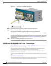
Step 1 Connect one end of the cable (Table 2-1) to the switch PoE port.
Step 2 Connect the other end of the cable to an RJ-45 connector on the other device. The port LED turns on
when both devices have established link.
The port LED is amber while STP discovers the topology and searches for loops. This process takes
about 30 seconds, and then the port LED turns green. If the LED is off, the other device might not be
turned on, there might be a cable problem, or there might be a problem with the adapter in the other
device. See
Chapter 3, “Troubleshooting,” for solutions to cabling problems.
Caution Noncompliant cabling or powered devices can cause a PoE port fault. Use only standard-compliant
cabling to connect Cisco prestandard IP Phones and wireless access points or IEEE 802.3af-compliant
devices. You must remove any cable or device that causes a PoE fault.
Step 3 Reconfigure and reboot the connected device if needed.
Step 4 Repeat Steps 1 through 3 to connect each device.
Note Many legacy powered devices, including older Cisco IP phones and access points that do not fully
support IEEE 802.3af, might not support PoE when connected to the switches by a crossover cable.
The autonegotiation and the auto-MDIX features are enabled by default on the switch.
With autonegotiation, the switch port configurations change to operate at the speed of the attached
device. If the attached device does not support autonegotiation, you can manually set the switch interface
speed and duplex parameters.
With auto-MDIX, the switch detects the required cable type for copper Ethernet connections and
configures the interface accordingly. If auto-MDIX is disabled, use
Table 2-1 to select the correct cable.
See the “Cables and Adapters” section on page B-3 for pinout descriptions.
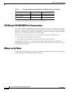
Ta b l e 2-1 Recommended Ethernet Cables (When Auto-MDIX is Disabled)
Device Crossover Cable
1
Straight-Through Cable
1
Switch to switch Yes No
Switch to hub Yes No