


2-15
Catalyst 2960-S Switch Hardware Installation Guide
OL-19732-04
Chapter 2 Switch Installation
Installing the Switch
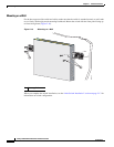
Attaching the RPS Connector Cover
Note The Catalyst 2960S-F48FPS-L, 2960S-F48LPS-L, 2960S-F24PS-L, 2960S-F48TS-L, 2960S-F24TS-L,
2960S-F48TS-S, and 2960S-F24TS-S switches do not have an RPS connector and a cover is not needed.
These models do not support RPS.
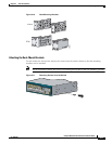
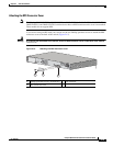
If you are not using an RPS with your switch, use the two Phillips pan-head screws to attach the RPS
connector cover to the back of the switch (
Figure 2-15).
Warning
If an RPS is not connected to the switch, install an RPS connector cover on the back of the switch.
Statement 265
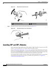
Figure 2-15 Attaching the RPS Connector Cover
1 Phillips pan-head screws (48-0482-01) 3 RPS connector
2 RPS connector cover
RA
T
I
NG
100-240~
12-6A, 50-60
Hz
21
3
206760