


12 Updates to Cisco AS5300 Universal Access Server Module Installation and Software Configuration Guides
Removing and Installing Cards and Modules
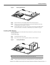
Installing VoIP Cards
To install a VoIP card:
Step 1 Remove the VoIP card from the ESD-preventive mat.
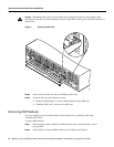
Step 2 Slide the VoIP card into the slot until it touches the backplane connector.
Step 3 Align the captive screws with their holes, and then seat the VoIP card completely.
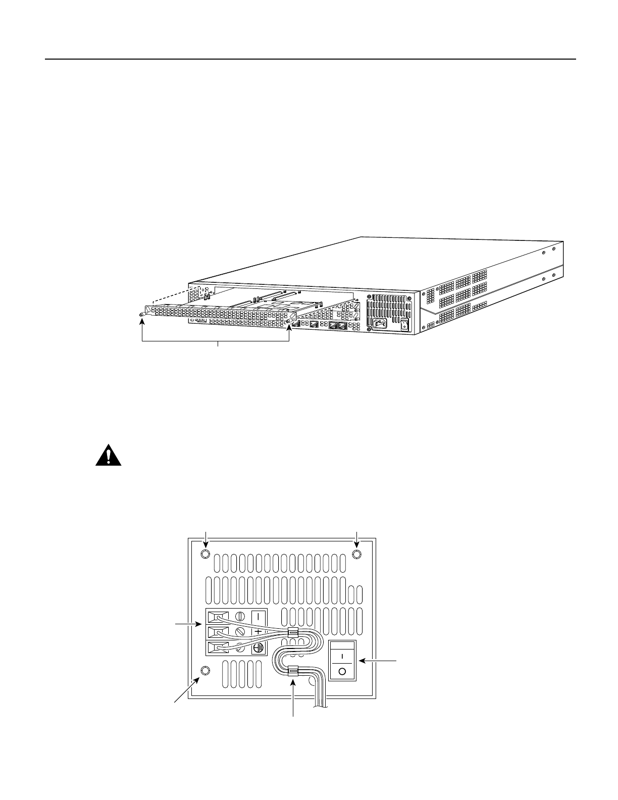
Step 4 Tighten the two captive screws (see Figure 8) to secure the VoIP card to the chassis.
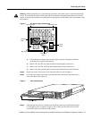
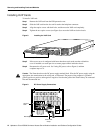
Figure 8 Installing the VoIP Card
Step 5 If the access server is configured with fewer than three cards, make sure that a blank slot
cover is installed over each open slot to ensure proper airflow inside the chassis.
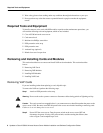
Step 6 Reconnect the AC power cord. Or, if using DC power, refer to Figure 9, and then
complete steps a to d.
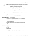
Caution The illustration shows the DC power supply terminal block. Wire the DC power supply using the
appropriate wire terminations at the wiring end, as illustrated. The proper wiring sequence is ground to
ground, positive to positive, and negative to negative. Note that the ground wire should always be connected
first and disconnected last.
Figure 9 DC Power Supply Connections
H11139
Captive screws
On/off
switch
H10720
Terminal
block
Strain-relief
clamp
Mounting screw