


Updates to Cisco AS5300 Universal Access Server Module Installation and Software Configuration Guides 9
Removing VoIP Cards
Warning Before performing any of the following procedures, ensure that power is removed from the DC
circuit. To ensure that all power is OFF, locate the circuit breaker on the panel board that services the DC
circuit, switch the circuit breaker to the OFF position, and tape the switch handle of the circuit breaker in the
OFF position.
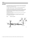
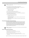
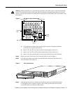
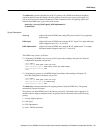
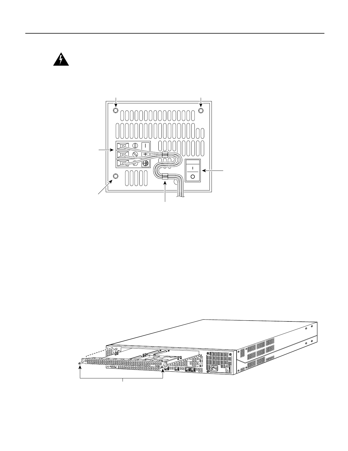
Figure 3 DC Power Supply Connections
(a)
Loosen the three locking screws for the negative, positive, and ground connectors
on the DC power supply terminal block.
(b) Remove the -48 VDC wire from the terminal block negative connector (-) .
(c) Remove the +48 VDC wire from the terminal block positive connector (+) .
(d) Remove the safety ground (green wire) from the terminal block ground connector.
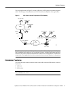
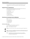
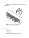
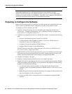
Step 3 On the rear panel of the access server, locate the VoIP card seen in Figure 4.
Step 4 Loosen the two captive screws that secure the VoIP card to the chassis until each screw is
free of the chassis. (See Figure 4.)
Figure 4 VoIP Card Removal
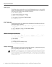
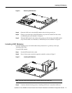
Step 5
Insert the card removal tool so that the slots in each arm of the tool are behind the shoulder
of each captive screw, as shown in Figure 5, and carefully pull the removal tool toward
you until the VoIP card slides free of the chassis.
On/off
switch
H10720
Terminal
block
Strain-relief
clamp
Mounting
screw
Mounting screw
Mounting
screw
H11139
Captive screws