


Send documentation comments to nexus5kdocs@cisco.com.
1-25
Cisco Nexus 5000 Series Hardware Installation Guide
OL-15902-01
Chapter 1 Overview
Cisco Nexus 5500 Platform Switches
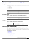
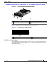
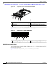
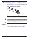
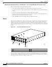
The Cisco Nexus 5548UP has front-to-back or back-to-front airflow. The Cisco Nexus 5548P has
front-to-back airflow only. Figure 1-25 shows the AC power supply, with two LEDs: one for power status
and one for failure condition.
Figure 1-25 AC Power Supply for the Cisco Nexus 5548 Switch
For information on each of the LEDs, see Table D-1 on page D-2. To see how combinations of these LED
states indicate specific conditions, see the “Power Supply Conditions” section on page E-2.
Note Never leave a power supply slot empty. If you remove a power supply, replace it with another one. If you
do not have a replacement power supply, leave the non functioning one in place until you can replace it.
For the specifications of this power supply, see Table B-11 on page B-4.
Caution The airflow direction should be the same for power suplies and fan modules.
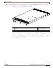
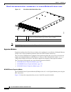
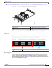
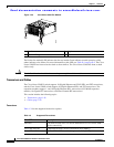
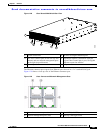
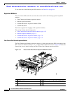
Fan Modules
The Cisco Nexus 5548 switch requires two fan modules. Each fan module has four fans. If more than
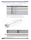
one fan fails in one of these modules, you must replace the module. Figure 1-26 identifies the
components that you use to install or troubleshoot these modules.
1 FAIL (top) and OK (bottom) LEDs 3 Release latch
2 Handle
239114
1 2 3