


Send documentation comments to nexus5kdocs@cisco.com.
2-6
Cisco Nexus 5500 Platform and Cisco Nexus 5000 Platform Hardware Installation Guide
OL-15902-02
Chapter 2 Installing the Cisco Nexus 5000 Series Switches
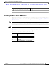
Installing the Switch
To install the switch in a rack or cabinet using the rack-mount kit provided with the switch, follow these
steps:
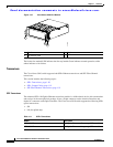
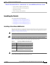
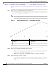
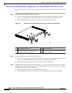
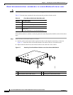
Step 1 Install the front rack-mount brackets on the chassis as follows:
a. Position a front rack-mount bracket on the side of the chassis with its four holes aligned to four of
the six screw holes on the front side of the chassis, and then use four M4 screws to attach the bracket
to the chassis. See Callouts 1 and 2 in Figure 2-1.
Note You can align any four of the holes in the front rack-mount bracket to four of the six screw holes
in the chassis. The holes that you use depend on the requirements of your rack.
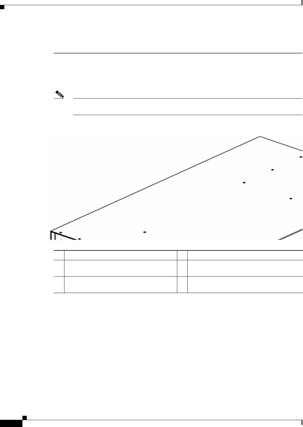
Figure 2-1 Attaching Rack-Mount Brackets to the Cisco Nexus 5596 Switch
b.
Repeat Step 1a with the other front rack-mount bracket on the other side of the switch.
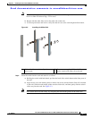
Step 2 Install the rear rack-mount guides on the chassis as follows:
a. Position a rear rack-mount bracket on the side of the chassis with its four holes aligned to four
of the six screw holes on the side of the chassis, and then use four M4 screws to attach the
bracket to the chassis. See Callout 4 in Figure 2-1.
b. Repeat Step 2a with the other rear rack-mount bracket on the other side of the switch.
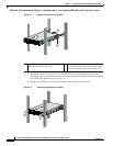
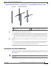
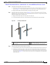
Step 3 Install the slider rails to the rack as follows:
a. Position the slider rails at the desired level on the back side of the rack and use two 12-24 screws
or two 10-32 screws, depending on the rack thread type, to attach the rails to the rack. See
Figure 2-2.
1 Front rack-mount bracket 4 Rear rack-mount guides
2 Four M4 screws used to attach each bracket to
the chassis
5 Alternative screw holes for the rack-mount
guide screws
3 Alternative screw holes for the front
rack-mount bracket screws