


Send documentation comments to nexus5kdocs@cisco.com.
2-26
Cisco Nexus 5500 Platform and Cisco Nexus 5000 Platform Hardware Installation Guide
OL-15902-02
Chapter 2 Installing the Cisco Nexus 5000 Series Switches
Starting the Switch
To power up the switch and verify hardware operation, follow these steps:
Step 1 Verify that empty power supply slots have filler panels installed, the faceplates of all modules are flush
with the front of the chassis, and the captive screws of the power supplies, fan module, and all expansion
modules are tight.
Step 2 Verify that the power supply and the fan modules are installed.
Note Depending on the outlet receptacle on your power distribution unit, you may need the optional
jumper power cord to connect the switch to your outlet receptacle. See the “Jumper Power Cord”
section on page C-9.
Step 3 Ensure that the switch is adequately grounded as described in the “Grounding the Switch” section on
page 2-17, and that the power cables are connected to outlets that have the required AC power voltages
(see the “Power Specifications” section on page B-3).
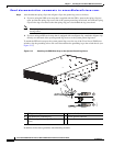
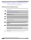
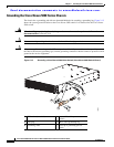
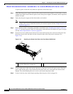
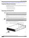
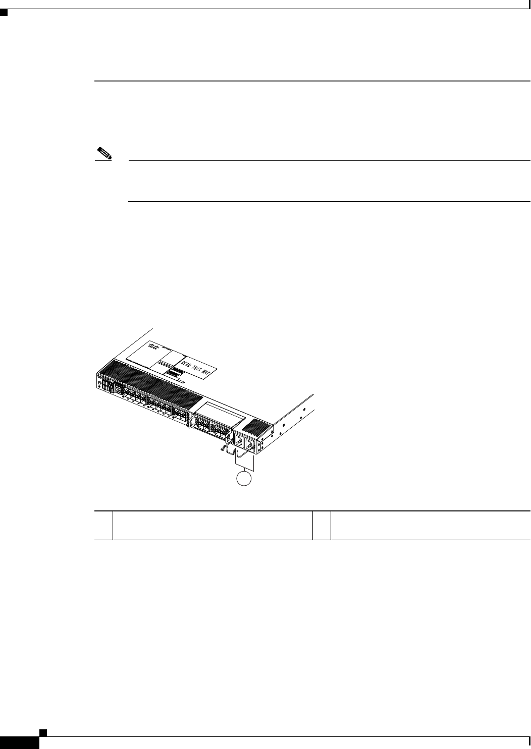
Step 4 For the Cisco Nexus 5020 switch and the Cisco Nexus 5010 switch, insert each end of the power clip
(from the accessory kit) into holes on tabs located on either side of the power connectors (see
Figure 2-16).
Figure 2-16 Attaching the Power Cord Clip to the Cisco Nexus 5010 Switch
Step 5
Connect each power cable to the power connectors on the chassis and an AC power source. Press the
power cable into the power clip to endure that the power cable stays connected to the chassis when
bumped. The switch should power on as soon as you connect the power cable.
Step 6 Listen for the fans; they should begin operating when the power cable is plugged in.
239212
1
1 Insert both clip ends into the tabs located on
either side of the power receptacles.