


7-23
Network Processing Engine and Network Services Engine Installation and Configuration
OL-4448-12
Chapter 7 NPE-G1 and NPE-G2 Installation and Configuration Information
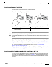
Installing the NPE-G1 or NPE-G2
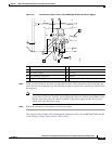
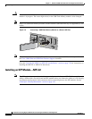
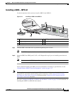
Installing a GBIC—NPE-G1
Use the instructions in this section to install a GBIC in the NPE-G1.
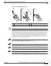
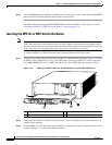
Figure 7-11 Installing a GBIC in the NPE-G1
Step 1 Turn the GBIC so the label side is up and the alignment groove is down.
Note The GBIC is keyed so that it cannot be inserted incorrectly.
Step 2 Insert the GBIC into GBIC port 0/1, 0/2, or 0/3. Repeat this step if you are installing more than one
GBIC.
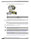
Note Do not remove the GBIC plugs until you are ready to install the cables.
You are finished installing the GBICs. For more information on cabling or specifications, see the
“Gigabit Ethernet GBIC Connection Equipment” section on page 5-13.
Note We strongly recommend cleaning all optical fiber connections before connecting optical cables to
equipment. For information about cleaning optical connectors, see the
Inspection and Cleaning
Procedures for Fiber-Optic Connections document and the Compressed Air Cleaning Issues for
Fiber-Optic Connections document.
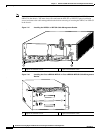
Go to the “Inserting the NPE-G1 or NPE-G2 into the Router” section on page 7-28 for instructions on
installing the NPE-G1 or NPE-G2 in the chassis.
1 GBIC 4 GBIC port 0/2
2 Alignment groove 5 Plug
3 GBIC port 0/1
ETHERNET 0/1
GBIC
RX
TX
GIGABIT ETHERNET 0/2
RJ45
GBIC
EN
RX
LINK
66774
1
3
5
2
4