


10-16
Network Processing Engine and Network Services Engine Installation and Configuration
OL-4448-12
Chapter 10 Configuration Tasks and Troubleshooting Information
Removing and Replacing an AC-Input or DC-Input Power Supply
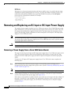
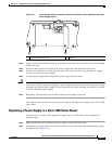
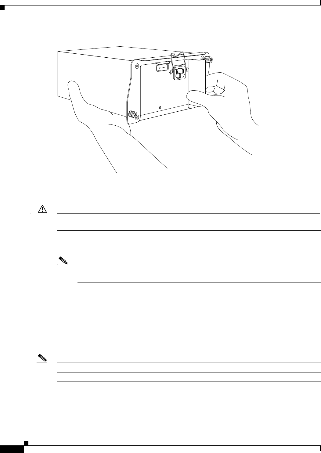
Figure 10-2 Holding the Power Supply—Cisco 7200 Series AC-Input Power Supply Shown
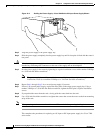
Step 3 Align the power supply to the power supply bay.
Step 4 Slide the power supply completely into the power supply bay until its faceplate is flush with the router’s
rear panel.
Caution When inserting a power supply into the router, do not use unnecessary force; slamming the power supply
into the bay can damage the connectors on the rear of the supply and on the midplane.
Step 5 Seat the power supply in the router by tightening its captive installation screws with a number 2 Phillips
or a 3/16-inch flat-blade screwdriver.
Note The power supply is not fully seated in the router midplane until you tighten its captive
installation screws (use a number 2 Phillips or a 3/16-inch flat-blade screwdriver).
Step 6 Repeat Step 1 through Step 5 for a second power supply (if present).
Step 7 If there is no second power supply, replace the filler plate on the empty power supply bay. Using a
number
2 Phillips or a 3/16-inch flat-blade screwdriver, tighten the filler plate’s captive installation
screws.
Step 8 If you pushed the router from the rack, slowly guide the router back into the rack.
Step 9 Use a 3/16-inch flat-blade screwdriver to tighten the screws that secure the router to the front mounting
strips of the rack.
Note When powering on the router, wait a minimum of 30 seconds before powering it off again.
This completes the procedures for replacing an AC-input or DC-input power supply in a Cisco 7200
series router.
H6433