


7-33
Network Processing Engine and Network Services Engine Installation and Configuration
OL-4448-12
Chapter 7 NPE-G1 and NPE-G2 Installation and Configuration Information
Installing the NPE-G1 or NPE-G2
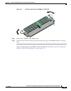
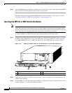
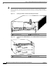
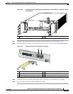
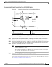
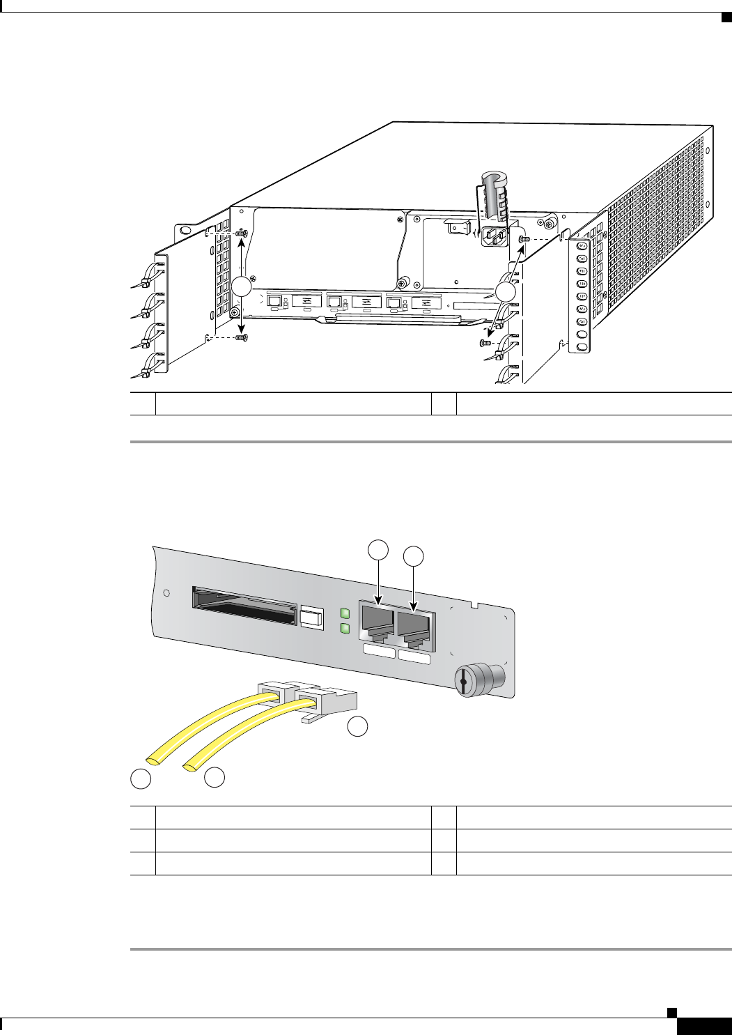
Figure 7-20 Installing the Rear Cable-Management Brackets with the NPE-G1 or NPE-G2—Router
Rear-Mounted
Step 1 Align the cable-management brackets with the rack-mount brackets as shown in Figure 7-20.
Step 2 Insert and tighten two screws for each bracket. The screws come with the cable-management brackets.
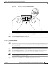
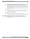
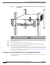
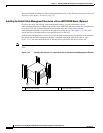
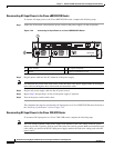
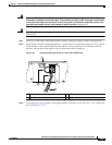
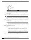
Figure 7-21 Attaching Console and Auxiliary Port Cables
Step 3 Insert the console and auxiliary RJ-45 cables into the interface ports on the NPE-G1 or NPE-G2.
Step 4 Place the cables through the cable-management brackets.
1 Screws
G
IGABIT ETH
ERNE
T 0/1
R
J
4
5
G
B
IC
E
N
R
X
T
X
L
IN
K
C
O
N
S
O
L
E
A
U
X
G
IGABIT ETH
ER
NET
0/1
R
J
4
5
G
B
IC
E
N
R
X
T
X
L
IN
K
GIGAB
IT E
THER
NET 0/1
R
J
4
5
G
B
IC
E
N
R
X
T
X
L
IN
K
C
P
U
R
E
S
E
T
C
O
M
P
A
C
T
F
L
A
S
H
P
O
W
E
R
O
N
S
L
O
T
A
C
T
IV
E
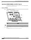
NETWORK PROCESSING ENGINE - G1
66750
EN
1
1
1 Console port 4 Cable to console terminal or DTE
2 Auxiliary port 5 Cable to modem or DCE
3 RJ-45 connectors
CONSOLE
AUX
CPU
RESET
COMPACT FLASH
POWER
ON
SLOT
ACTIVE
NETWORK PROCESSING ENGINE - G1
66777
1
2
3
4
5