


9-10
Network Processing Engine and Network Services Engine Installation and Configuration
OL-4448-12
Chapter 9 Removing and Installing the NPE or NSE
Removing and Replacing the NPE or NSE
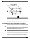
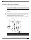
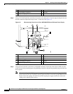
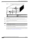
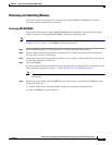
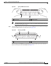
Figure 9-6 Cisco 7200 Series NPE or NSE Captive Installation Screws and Handle
Step 4 Using a 3/16-inch flat-blade screwdriver, loosen the screws that secure the router to the front mounting
strips of the rack.
Step 5 Position at least one person in front of the rack to support the front underside of the router.
Step 6 From the rear of the rack, carefully push the front of the router out of the rack until there is enough
clearance to remove the network processing engine.
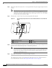
Step 7 Grasp the network processing engine handle and carefully pull the network processing engine from its
chassis slot.
Caution Handle the network processing engine by the carrier edges and handle only; never touch the printed
circuit board components or connector pins.
Step 8 Place the NPE or NSE on an antistatic surface with its printed circuit board components facing upward,
or in a static shielding bag. If you are returning the network processing engine to the factory,
immediately place it in a static shielding bag.
This completes the procedure for removing an installed NPE or NSE. For instructions on installing the
NPE or NSE, go to the
“Installing the NPE or NSE” section on page 9-21.
1 Captive installation screw 3 Network processing engine or network
services engine
2 Handle 4 AC-input power supply
66605
NETW
ORK PROCESSING ENGINE-300
1 2 3 4