


7-32
Network Processing Engine and Network Services Engine Installation and Configuration
OL-4448-12
Chapter 7 NPE-G1 and NPE-G2 Installation and Configuration Information
Installing the NPE-G1 or NPE-G2
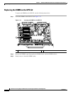
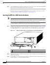
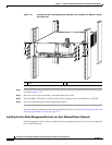
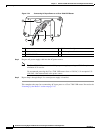
Figure 7-19 Installing the Rear Cable-Management Brackets with an NPE-G1 or NPE-G2—Router
Front-Mounted
Step 1 If the back of the router protrudes from the rack, place the cable-management brackets against the router
as shown in
Figure 7-19.
Step 2 Insert two screws into each bracket, and tighten them to the router.
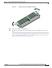
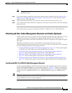
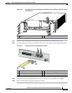
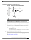
Step 3 Insert the GBIC, SFP module, or RJ-45 cables into the interface ports on the NPE-G1 or NPE-G2.
Step 4 Place the cables through the cable-management brackets.
You have finished installing the cable-management brackets. Go to the “Reconnecting Input Power and
Powering Up the Router” section on page 7-35.
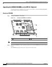
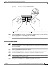
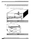
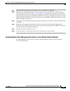
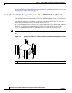
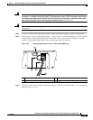
Installing the Rear Cable-Management Brackets on a Rear-Mounted Router (Optional)
Use the instructions in this section to attach the cable-management brackets if you have a rear-mounted
Cisco
7200 VXR router.
1 Screws
H6423
GIGABIT ETHERNET 0/1
R
J
4
5
G
B
IC
E
N
R
X
T
X
L
IN
K
C
O
N
S
O
L
E
A
U
X
GIGABIT ETHERNET 0/1
R
J
4
5
G
B
IC
E
N
R
X
T
X
L
IN
K
GIGABIT ETHERNET 0/1
R
J
4
5
G
B
IC
E
N
R
X
T
X
L
IN
K
C
P
U
R
E
S
E
T
C
O
M
P
A
C
T
F
L
A
S
H
P
O
W
E
R
O
K
S
L
O
T
A
C
T
IV
E
N
ET
W
O
R
K
PR
O
C
E
S
S
IN
G
E
N
G
IN
E
- G
1
66749
1
1