


2-15
Optical Transport Turn-Up and Test Guide
78-14964-01
Chapter 2 Quick Installation Procedures
Installing Cisco ONS 15540 ESPx Hardware
Connecting the Console Port
The console port is a female, DCE (data communications equipment), DB-25 receptacle used for
connection to a console terminal or modem. To connect cables to the console port, follow these steps:
Step 1 Place the DB-25 connector in front of the console port on the processor card faceplate.
Step 2 Align the male DB-25 connector with the female console port.
Step 3 Gently push the DB-25 connector into the console port and secure it into place by tightening the side
screws on the DB-25 connector.
Step 4 Route the fiber cables down through the cutout holes on the cable management tray out of the right side
of the shelf assembly.
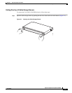
Installing Mux/Demux Motherboards and Mux/Demux Modules
The Cisco ONS 15540 ESPx chassis uses one optical mux/demux motherboard for unprotected
operation or two per system for protected operation.
Installing Mux/Demux Motherboards
You can install up to two mux/demux motherboards into slot 0 and slot 1. Perform the following
procedure to install a mux/demux motherboard.
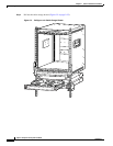
Step 1 Insert the card carefully into the chassis slot. Guide the upper and lower edges of the motherboard or
processor card in the tracks until its connectors come into contact with the backplane.
Step 2 Use your thumb and forefinger of each hand to simultaneously push the card in until it is fully seated in
the backplane connector.
Step 3 Use a 3/16-inch flat-blade screwdriver to tighten the captive installation screws.
Installing 4-Channel or 8-Channel Mux/Demux Modules
This section describes the procedure for installing a 4-channel or 8-channel mux/demux module in the
Cisco ONS 15540 ESPx. Up to four 4-channel or 8-channel mux/demux modules can be installed in a
mux/demux motherboard.