


2-23
Optical Transport Turn-Up and Test Guide
78-14964-01
Chapter 2 Quick Installation Procedures
Installing Cisco ONS 15540 ESPx Hardware
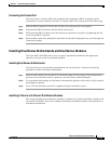
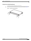
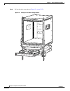
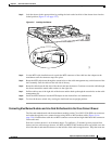
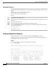
Step 3 Lock the drawer in the open position by pushing the latch at the back left of the drawer down into the
locked position (Figure 2-3 on page 2-23).
Figure 2-3 Locking the Drawer
Step 4 Use the MTP cable installation tool to push the MTP connector of the cable into the adapter on the
mux/demux until the connector snaps into place.
Step 5 Route the MTP cable down through the cutout holes on the cable management tray on the bottom of the
shelf assembly. Pull the cable out the left side of the tray.
Step 6 Route the cable down the left side of the chassis and into the drawer. Continue to route the cable through
the drawer around the round cable retainers to the right side.
Step 7 Pull the cable up out of the right side of the drawer and the back up through the cutout holes on the cable
management tray.
Step 8 Insert the MTP connector into the MTP adapter on the desired line card motherboard.
Step 9 To close the drawer, unlock it by moving the latch back into an upright position.
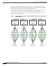
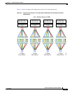
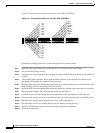
Connecting Mux/Demux Modules and Line Card Motherboards to the Cross Connect Drawer
The line card motherboards and the mux/demux modules on the Cisco ONS 15540 ESPx can connect to
each other through the cross connect drawers using MTP-to-MU breakout cables (Figure 2-6 on
page 2-26). Each breakout cable has an MTP connector on one end and eight individual MU connectors
on the other end.
Each cross connect drawer is an 8-channel drawer. To configure a 32-channel system you need four
drawers and two cable storage drawers. All MTP and MTP to MU breakout cables are pulled out to the
left of the chassis and enter the drawers on the left side of the cable storage drawers. They then route out
79527