


2-18
Optical Transport Turn-Up and Test Guide
78-14964-01
Chapter 2 Quick Installation Procedures
Installing Cisco ONS 15540 ESPx Hardware
Step 3 Use the handles to push the line card motherboard in until it is fully seated in the backplane connector.
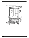
Step 4 Install blank covers into the unused motherboard slots.
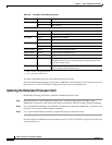
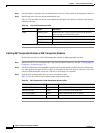
Table 2-8 lists the LEDs on the line card motherboard faceplate, their default conditions, and what the
conditions indicate.
Installing SM Transponder Modules or MM Transponder Modules
Perform this procedure to install SM transponder modules or MM transponder modules.
Step 1 Remove the dust covers from the module, and clean the optical connectors. See the “Cleaning Optical
Connectors” section on page 2-28.
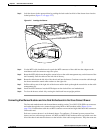
Step 2 Lift the latch handle on the transponder module and insert the module carefully into the motherboard
slot while guiding the upper and lower edges of the module in the tracks until its connectors come into
contact with the backplane connectors. You hear a click when it is connected.
Step 3 Push the latch on the module down to secure the module in place.
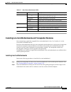
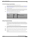
Table 2-9 lists the LEDs for the extended range transponder module.
Table 2-8 Line Card Motherboard LEDs
LED Status Description
Status Blinking green Motherboard has a good system clock from the primary
processor and is out of the reset state.
Solid green Software initialization is successful.
Orange System clock is not present. Board is unavailable.
Off Board failure
Table 2-9 SM Transponder or MM Transponder Module LEDs
LED Status Description
LCL RX OK Green Data is received on the client side.
TRUNK RX OK Green Data is received on the trunk side.
LCL TX ENABLE Green Client side transmit laser is enabled.
TRUNK TX ENABLE Green Trunk side transmit laser is enabled.