


2-27
Optical Transport Turn-Up and Test Guide
78-14964-01
Chapter 2 Quick Installation Procedures
Common Installation Procedures
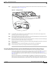
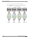
Step 14 Connect the MU breakout end of the cable to the bottom half of the desired adapter mux/demux
connections on the inner side of the cross connect panel. These are color coded and should be connected
by matching the color on the panel to the colored wires out of the transition box. See Figure 2-6.
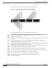
Step 15 Connect the line card motherboard to the cross connect panel in the same way as the mux/demux cabling
on the left hand side of the chassis as well. Connect the MU breakout end of the cable to the top half of
the connections on the inner side of the cross connect panel.
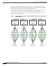
Connecting Mux/Demux Modules and Transponder Modules
To connect the mux/demux modules and transponder modules in the cross connect drawer, use the MU
to MU cables. Each cross connect drawer is an eight-channel drawer. To configure a 32-channel system
you need four drawers and two cable storage drawers. MTP and MTP to MU breakout cables are pulled
out to the left of the chassis and enter the drawers on the left side of the cable storage drawers. Route
out of the right of the cable storage drawer and enter the cross connect drawers through the right side
and connect to their destination connector.
Follow these steps to connect mux/demux and transponders.
Step 1 Connect one end of the MU to MU cable to the top half of the desired mux/demux connections on the
outside of the cross connect panel.
Step 2 Connect the other end of the same MU to MU cable to the bottom half of the desired line card
motherboard connection on the outside of the cross connect panel.
Step 3 Push the panel down and lock it by pushing the tabs down.
Step 4 Push the drawer in when your connections are completed.
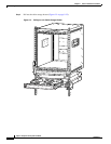
Common Installation Procedures
After completing the installation procedures for the Cisco ONS 15540 ESP or Cisco ONS 15540 ESPx,
perform these procedures common to both platforms:
• Shelf Grounding Procedure, page 2-27
• Cleaning the Shelf, page 2-28
• Powering Up the Chassis, page 2-29
• Verifying Installation of Hardware, page 2-30
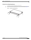
Shelf Grounding Procedure
This section describes how to connect the Cisco ONS 15540 to earth ground. You must complete this
procedure before connecting system power or powering up your shelf.
Tip If you use the cable management guides, install the grounding equipment after you install the top cable
management guide.