


2-9
Optical Transport Turn-Up and Test Guide
78-14964-01
Chapter 2 Quick Installation Procedures
Installing Cisco ONS 15540 ESP Hardware
Step 3 Lift the latch handle on the extended range transponder module and insert the module carefully into the
motherboard slot while guiding the upper and lower edges of the module in the tracks until its connectors
come into contact with the backplane connectors. You hear a click when it is connected.
Step 4 Push the latch on the module down to secure the module in place.
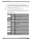
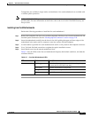
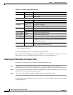
Table 2-5 lists the LEDs for the extended range transponder module.
Cabling Transponder Modules
To install fiber-optic cables in the Cisco ONS 15540 ESP, a fiber cable with the corresponding connector
type must be connected to the transmit and receive ports on the modules. On Cisco ONS 15540 optical
ports, the top connector is Transmit and the bottom connector is Receive. Label the transmit and receive
and the working and protection fibers at each end of the fiber span to avoid confusion with cables that
are similar in appearance.
Step 1 Place the connector in front of the connection point on the transponder module faceplate. Each
transponder module has at least one transmit and one receive connector to create an optical carrier port.
Step 2 Align the keyed ridge of the cable connector with the receiving slot on the faceplate connection point.
Gently push the cable connector into the faceplate connection point until the connector snaps into place.
Step 3 Route fiber cables through the cable retaining clips on the optical card faceplate into the cable
management tray on the bottom of the shelf assembly.
Step 4 Route the fiber cables from the cable management tray out of the right side of the shelf assembly through
cutout holes from the cable management tray.
Cabling Mux/Demux Modules
This section describes the connections between pairs of mux/demux modules and between mux/demux
modules and mux/demux motherboards in the Cisco ONS 15540 ESP. The assumption is made that the
motherboard and modules are already installed and checked.
Table 2-5 Extended Range Transponder Module LEDs
LED Status Description
CLIENT RX Green Data is received on the client side.
TRUNK RX Green Data is received on the trunk side.
CLIENT TX Green Client side transmit laser is enabled.
TRUNK TX Green Trunk side transmit laser is enabled.