


2-5
Optical Transport Turn-Up and Test Guide
78-14964-01
Chapter 2 Quick Installation Procedures
Installing Cisco ONS 15540 ESP Hardware
Installing Mux/Demux Motherboards and Mux/Demux Modules
The Cisco ONS 15540 ESP chassis uses one optical mux/demux motherboard for unprotected operation
or two per system for protected operation.
Installing Mux/Demux Motherboards
You can install up to two motherboards into slot 0 and slot 1. Perform the following procedure to install
a mux/demux motherboard.
Note In Cisco ONS 15540 ESP systems, there are additional rules for slot placement of mux/demux modules
and line cards. Refer to the Cisco ONS 15540 ESP Planning and Design Guide.
Step 1 Remove the backplane side dust covers and transponder side dust covers from the motherboards, and
clean the optical connectors. See the “Cleaning Optical Connectors” section on page 2-28.
Step 2 Insert the card carefully into the chassis slot. Guide the upper and lower edges of the motherboard or
processor card in the tracks until its connectors come into contact with the backplane.
Step 3 Use your thumb and forefinger of each hand to simultaneously push the card in until it is fully seated in
the backplane connector.
Step 4 Use a 3/16-inch flat-blade screwdriver to tighten the captive installation screws.
Step 5 Install blank covers into the unused motherboard slots.
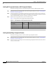
Note Mux/demux motherboards without OSC have no LEDs.
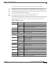
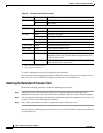
Table 2-2 Mux/Demux Motherboard LEDs
LED Status Description
Status Blinking green Motherboard has a good system clock from the primary
processor and is out of the reset state.
Solid green Software initialization is successful.
Orange System clock is not present. Board is unavailable.
Off Board failure
Tx Solid green OSC is present and the optical laser output is enabled.
Off OSC is not present and the optical laser output is disabled.
Rx Solid green OSC is present and the receiver is enabled.
Off OSC is not present and the receiver is disabled.