


Cisco 7200 Series and the PA-E3 5-3
Installing a Port Adapter
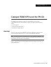
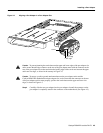
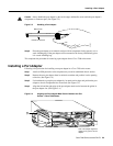
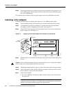
Caution Always handle the port adapter by the carrier edges and handle; never touch the port adapter’s
components or connector pins. (See Figure 5-3.)
Figure 5-3 Handling a Port Adapter
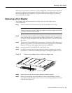
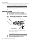
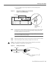
Step 6
Place the port adapter on an antistatic surface with its components facing upward, or in a
static shielding bag. If the port adapter will be returned to the factory, immediately place
it in a static shielding bag.
This completes the procedure for removing a port adapter from a Cisco 7200 series router.
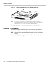
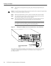
Installing a Port Adapter
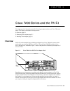
Following is the procedure for installing a new port adapter in a Cisco 7200 series router:
Step 1 Attach an ESD-preventive wrist strap between you and an unfinished chassis surface.
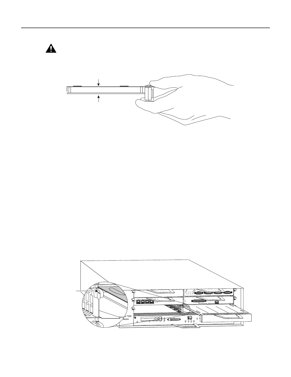
Step 2 Remove the new port adapter from its antistatic container and position it at the opening
of the slot. (See Figure 5-4.)
Step 3 Use both hands to grasp the port adapter by its metal carrier edges and position the port
adapter so that its components face downward. (See Figure 5-3.)
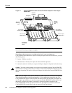
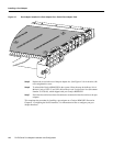
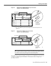
Step 4 Align the left and the right edge of the port adapter metal carrier between the guides in
the port adapter slot. (See Figure 5-4.)
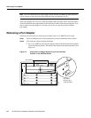
Figure 5-4 Aligning the Port Adapter Metal Carrier Between the Slot
Guides
—Cisco 7206 Shown
H6420
Metal carrier
Printed circuit board
H6597
MII
EN
RJ45
EN
RJ45
LINK
1O PWR
OK
RJ-45
CPU RESET
FAST ETHERNET INPUT/OUTPUT CONTROLLER
ENABLED
PCMCIA
EJECT
SLOT 0
SLOT 1
FE MII
2
4
6
1
3
5
ETHERNET 10BT
ENABLED
0
2
1
3
LINK
0
1
2
3
ENABLED
MII
LINK
RJ45
FAST ETHERNET
0
TOKEN RING
0
1
2
3
Slot
guide
Note: This adapter alignment
applies to any port or service
adapter.