


Removing a Port Adapter
PA-E3 Serial Port Adapter Installation and Configuration
7-2
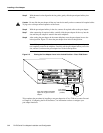
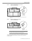
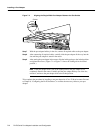
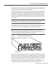
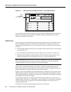
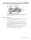
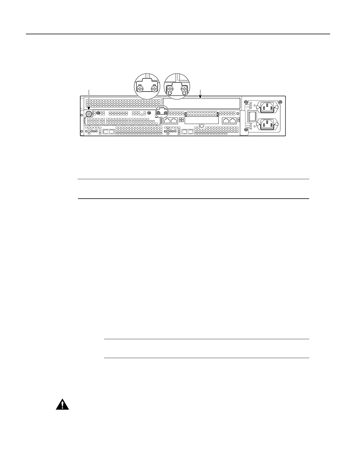
Figure 7-2 Cisco 7140 Series Router—Port Adapter Slot 4 Location
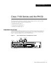
Depending on your circumstances, you might need to install a new port adapter in a Cisco 7100
series routeror replace afailed portadapter inthe field.All port adaptersavailable forthe Cisco 7100
series connect directly to the router and are locked into position by a locking tab with two screws
(see Figure 7-1 or Figure 7-2). You need a number 2 Phillips screwdriver to loosen the screws.
Note Cisco 7100 series routers support online insertion and removal (OIR); therefore, you do not
have to power down the router when removing and replacing a port adapter.
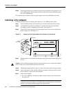
When a port adapter slot is notin use, a blank port adapter must fill the emptyslot to allow the router
to conform to EMI emissions requirements and to allow proper airflow across the port adapters. If
you plan to install a new port adapter in a slot that is not in use, you must first remove a blank
port adapter.
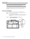
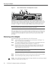
Removing a Port Adapter
Follow these steps to remove a port adapter from a Cisco 7100 series router:
Step 1 Attach an ESD-preventive wrist strap between you and the chassis. (See Figure 7-1 or
Figure 7-2 for the location of the ESD plug.)
Step 2 Use a number 2 Phillips screwdriver to loosen the screws on the locking tab; then slide
the tab down to the unlocked position. (See Figure 7-1 or Figure 7-2.)
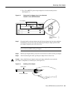
Step 3 Grasp the handle on the port adapter and pull the port adapter from the router, about
halfway out of its slot. If you are removing a blank port adapter, pull the blank port
adapter completely out of the chassis slot.
Note As you disengage the port adapter from the router, OIR administratively shuts
down all active interfaces on the port adapter.
Step 4 With the port adapter halfway out of the slot, disconnect all cables from the port adapter.
Step 5 After disconnecting the cables, pull the port adapter from its chassis slot.
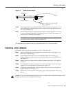
Caution Always handle the port adapter by the carrier edges and handle; never touch the port adapter’s
components or connector pins. (See Figure 7-3.)
AC OK
DC OK
OTF
AC OK
DC OK
OTF
SLOT 0 SLOT 1
5
155 - MM
RX
RX
EN
CEL CARALM
TX
I
155 - MM
CONS
FE 0 / 0 FE
ACT
0 / 1
AUX
0
2
RX
7140 - 2MM3
RX
EN
CEL CARALM
TX
ACT
LNK
0
LNK
1
PWR
SYS
RDY
Slot 4
Unlocked
Locked
22134
ESD plug