


Configuring the PA-E3 Interfaces 8-5
Catalyst RSM/VIP2 Ports
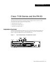
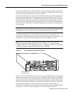
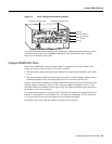
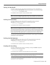
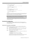
Figure 8-3 Cisco 7505 Serial Port Number Example
You can identify interface ports by physically checking the slot/port-adapter/interface port location
on the back of the router or by using show commands to display information about a specific
interface or all interfaces in the router.
Catalyst RSM/VIP2 Ports
In the Catalyst RSM/VIP2, each port adapter address is composed of a two-part number in the
format port adapter number/interface port number, as follows:
• The first number identifies thephysical port adapter slot on the Catalyst RSM/VIP2, and is either
0 or 1.
• The second number identifies the interface port on each E3 serial port adapter, which is always
numbered as interface 0 for the one-port PA-E3 and 0 or 1 for the two-port PA-2E3.
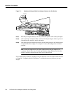
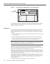
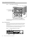
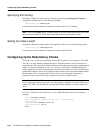
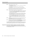
Figure 8-4 shows the port adapters ona Catalyst RSM/VIP2 installed in a Catalyst 5509 switch.The
first port adapter slot number is always 0. The second port adapter slot number is always 1. The
individual interface port numbers always begin with 0. The number of additional ports depends on
the number of ports on a port adapter.
For example, the serial port on a one-port PA-E3 in the first port adapter slot is numbered 0/0. (See
Figure 8-4.) If the PA-E3 is in port adapter slot 1, this same port is numbered 1/0. The serial ports
on a two-port PA-2E3 in the first port adapter slot are numbered 0/0 and 0/1.
Port adapters can occupy either port adapter slot; there are no restrictions.
H10610
ENABLED
RCLK
XMTR
RCVR
FERF
OOF
RL
LL
AIS
E3 SERIAL
Slot 0
Slot 1
Slot 2
Slot 3
Interface
processor
slots
EJECT
SLOT 0
SLOT 1
NORMAL
CPU HALT
RESET
CONSOLE
ROUTE SWITCH PROCESSOR
PA-E3 (port numbers 3/1/0)PA-E3 (port number 3/0/0)
ENABLED
RCLK
XMTR
RCVR
FERF
OOF
RL
LL
AIS
E3 SERIAL