


6
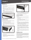
Connecting the Switch
48-Port 10/100 + 4-Port Gigabit Switch with WebView and Power over Ethernet
Chapter 3
Desktop Placement
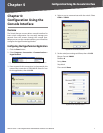
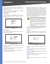
Attach the rubber feet to the recessed areas on the
bottom of the Switch.
Place the Switch on a desktop near an AC power
source.
Keep enough ventilation space for the switch and
check the environmental restrictions mentioned in
“Appendix C: Specifications” as you are placing the
Switch.
Connect the Switch to network devices according to
the Hardware Installation instructions below.
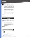
Attaching the Switch’s Rubber Feet
Rack-Mount Placement
To rack-mount the Switch in any standard 19-inch rack,
follow the instructions described below.
Place the Switch on a hard flat surface with the front
panel faced towards your front side.
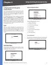
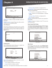
Attach a rack–mount bracket to one side of the Switch
with the supplied screws and secure the bracket
tightly.
Attaching the Brackets
Follow the same steps to attach the other bracket to
the opposite side.
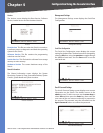
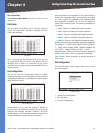
After the brackets are attached to the Switch, use
suitable screws to securely attach the brackets to any
standard 19-inch rack.
•
•
•
•
1.
2.
3.
4.
Mounting in Rack
Connect the Switch to network devices according to
the Hardware Installation instructions below.
Hardware Installation
To connect network devices to the Switch, follow these
instructions:
Make sure all the devices you will connect to the Switch
are powered off.
Connect a Category 5 Ethernet network cable to one
of the numbered ports on the Switch.
Connect the other end to a PC or other network
device.
Repeat steps 2 and 3 to connect additional devices.
If pre-standard or 802.3af-compliant PoE devices are
connected to the Switch’s 10/100 ports, the Switch
automatically supplies the required power.
If you are using a miniGBIC port, then connect a
miniGBIC module to the miniGBIC port. For detailed
instructions, refer to the module’s documentation.
Connect the supplied power cord to the Switch’s
power port, and plug the other end into an electrical
outlet. When connecting power, always use a surge
protector.
Power on the devices connected to the Switch. Each
active port’s corresponding LED will light up on the
Switch.
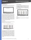
Uplinking the Switch
To uplink the Switch, connect one end of a Cat 5 (or better)
Ethernet network cable into one of the 4 gigabit ports, and
then connect the other end of the cable into the peripheral
device’s uplink port. MDI/MDIX will automatically detect
the speed and cable type.
The hardware installation is complete. Proceed to “Chapter
4: Configuration using the Console Interface”, for directions
on how to set up the Switch.
5.
1.
2.
3.
4.
5.
6.
7.