


Chapter 5
Configuring the Switch
31
48-Port 10/100 + 4-Port Gigabit Switch with WebView and Power over Ethernet
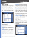
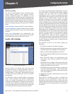
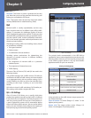
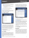
Generate This button is used to generate the host key
pair. Note that you must first generate the host key pair
before you can enable the SSH server.
Clear This button clears the host key from both volatile
memory (RAM) and non-volatile memory (Flash).
QoS
Network traffic is usually unpredictable, and the only
basic assurance that can be offered is best effort traffic
delivery. To overcome this challenge, Quality of Service
(QoS) is applied throughout the network. This ensures that
network traffic is prioritized according to specified criteria,
and that specific traffic receives preferential treatment.
QoS in the network optimizes network performance and
entails two basic facilities:
Classifying incoming traffic into handling classes, based
on an attribute, including:
The ingress interface
Packet content
A combination of these attributes
Providing various mechanisms for determining the
allocation of network resources to different handling
classes, including:
The assignment of network traffic to a particular
hardware queue
The assignment of internal resources
Traffic shaping
The terms Class of Service (CoS) and QoS are used in the
following context:
CoS provides varying Layer 2 traffic services. CoS refers to
classification of traffic to traffic-classes, which are handled
as an aggregate whole, with no per-flow settings. CoS is
usually related to the 802.1p service that classifies flows
according to their Layer 2 priority, as set in the VLAN
header.
QoS refers to Layer 2 traffic and above. QoS handles per-
flow settings, even within a single traffic class.
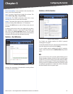
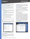
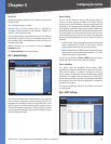
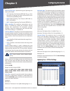
QoS > CoS Settings
Class of Service (CoS) allows you to specify which data
packets have greater precedence when traffic is buffered
in the Switch due to congestion. The Switch supports CoS
with four priority queues for each port. Data packets in
a port’s high-priority queue will be transmitted before
those in the lower-priority queues. You can set the default
priority for each interface, and configure the mapping of
frame priority tags to the Switch’s priority queues.
•
•
•
•
•
•
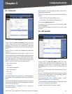
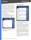
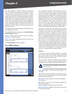
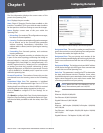
QoS > Cos Settings
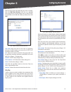
The priority levels recommended in the IEEE 802.1p
standard for various network applications are shown in the
following table. However, you can map the priority levels
to the Switch’s output queues in any way that benefits
application traffic for your own network.
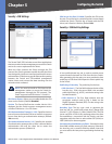
Priority Level Mappings
Priority Level Traffic Type
1 Background
2 (Spare)
0 (default) Best Effort
3 Excellent Effort
4 Controlled Load
5 Video, less than 100 ms latency and jitter
6 Voice, less than 10 ms latency and jitter
7 Network Control
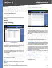
CoS to Queue
Assign priorities to the traffic classes (output queues) for
the selected interface.
Class of Service CoS value. (Range: 0-7, where 7 is the
highest priority queue)
Queue (0-3) The output priority queue. (Range: 0-3,
where 3 is the highest CoS priority queue)