


10
Catalyst 6500 Series Switch and Cisco 7600 Series Router CMM Installation and Verification Note
78-14107-07
Installing and Removing the CMM
To install the CMM into the Catalyst 6500 series switch or the Cisco 7600 series router, perform these
steps:
Step 1 Make sure that you take the necessary precautions to prevent ESD damage.
Step 2 Choose a slot for the CMM.
Step 3 Verify that there is enough clearance to accommodate any interface equipment that you will connect
directly to the module ports. If possible, place modules between empty slots that contain only module
filler plates.
Step 4 Verify that the captive installation screws are tightened on all modules that are installed in the chassis.
This action ensures that the EMI gaskets on all modules are fully compressed to maximize the opening
space for the replacement module.
Note If the captive installation screws are loose, the EMI gaskets on the installed modules will push
adjacent modules toward the open slot, reducing the opening size and making it difficult to
install the replacement module.
Step 5 Remove the module filler plate by removing the two Phillips pan-head screws from the filler plate. (To
remove a module, refer to the “Removing the CMM” section on page 16.)
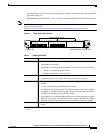
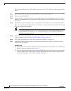
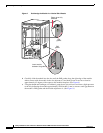
Step 6 Fully open both ejector levers on the new or replacement module. (See Figure 5.)
Step 7 Depending on the orientation of the slots in the chassis (horizontal or vertical), perform one of the
following sets of substeps:
Horizontal slots
a. Position the module in the slot. Make sure that you align the sides of the module carrier with the slot
guides on each side of the slot. (See Figure 5.)
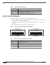
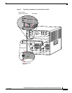
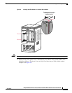
a. Carefully slide the module into the slot until the EMI gasket along the top edge of the module makes
contact with the module in the slot above it and both ejector levers have closed to approximately
45 degrees with respect to the module faceplate. (See Figure 6.)