


16
Catalyst 6500 Series Switch and Cisco 7600 Series Router CMM Installation and Verification Note
78-14107-07
Installing and Removing the CMM
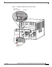
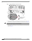
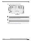
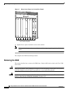
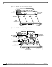
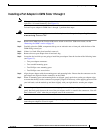
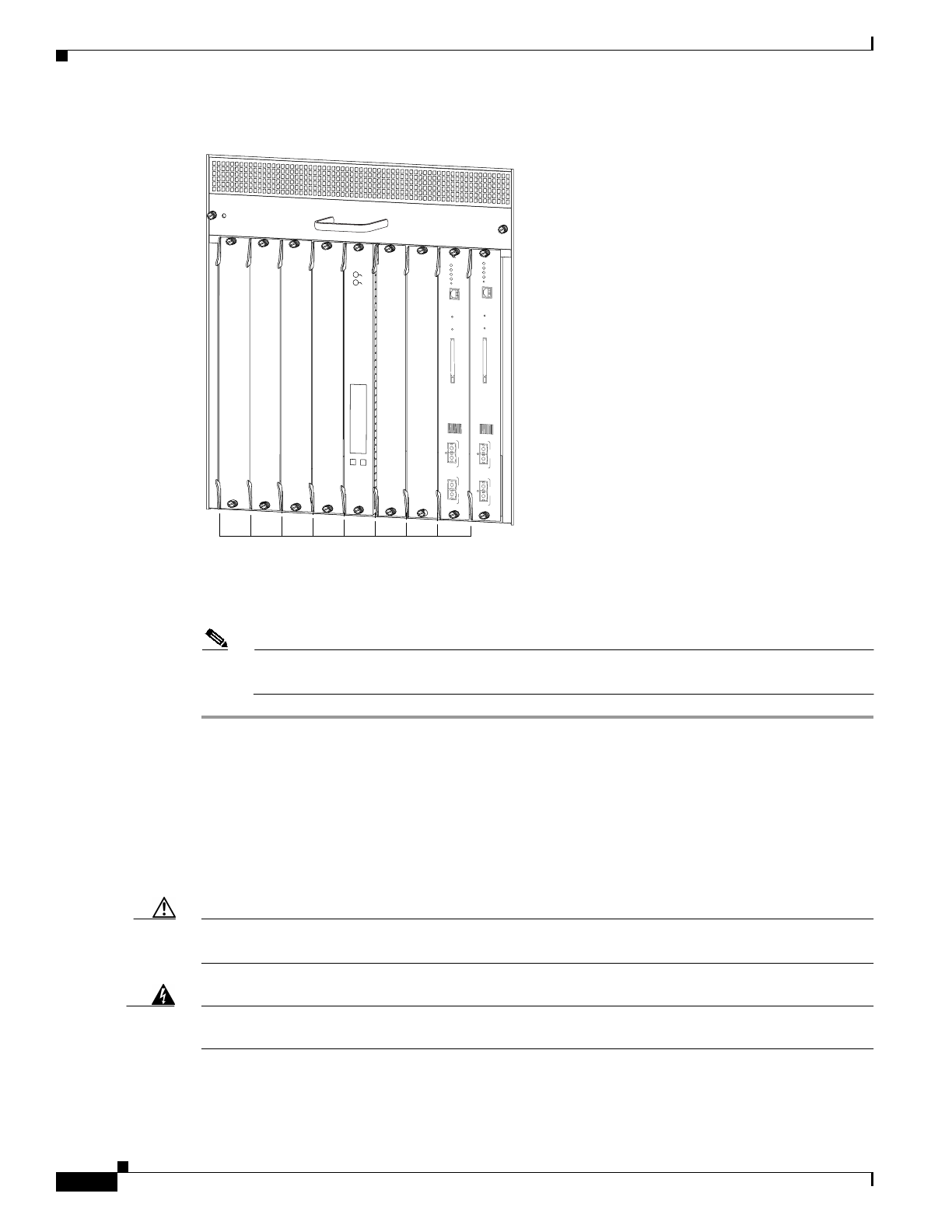
Figure 10 Ejector Lever Closure in a Vertical Slot Chassis
e. Tighten the two captive installation screws on the module.
Note Make sure that the ejector levers are fully closed before tightening the captive installation
screws.
This completes the CMM installation procedure.
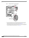
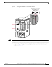
Removing the CMM
This section describes how to remove the CMM from a Catalyst 6500 series switch or the Cisco 7600
series router.
Caution During this procedure, wear grounding wrist straps to avoid ESD damage to the module. Do not directly
touch the backplane with your hand or any metal tool, or you could shock yourself.
Warning
Invisible laser radiation may be emitted from disconnected fibers or connectors. Do not stare into
beams or view directly with optical instruments. Statement 1051
FAN
STATUS
SELECT
NEXT
24 PORT 100FX
WS-X6224
STATUS
ACTIVE
SUPERVISOR2
WS-X6K-SUP2-2GE
STATUS
SYSTEM
CONSOLE
PW
R MGMT
RESET
CONSOLE
CONSOLE
PORT
MODE
PCMCIA EJECT
PORT 1
PORT 2
Switch Load
100%
1%
SUPERVISOR2
WS-X6K-SUP2-2GE
STATUS
SYSTEM
CONSOLE
PWR MGMT
RESET
CONSOLE
CONSOLE
PORT
MODE
PCMCIA
EJECT
PORT 1
PORT 2
Switch Load
100%
1%
63587
All ejector levers flush
with module faceplate