


14
Catalyst 6500 Series Switch and Cisco 7600 Series Router CMM Installation and Verification Note
78-14107-07
Installing and Removing the CMM
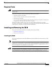
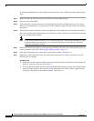
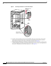
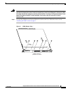
Figure 8 Positioning the Module in a Vertical Slot Chassis
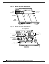
b. Carefully slide the module into the slot until the EMI gasket along the right edge of the module
makes contact with the module in the slot adjacent to it and both ejector levers have closed to
approximately 45 degrees with respect to the module faceplate. (See Figure 9.)
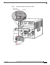
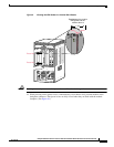
c. Using the thumb and forefinger of each hand, grasp the two ejector levers and exert a slight pressure
to the left, deflecting the module approximately 0.040 inches (1 mm) to create a small gap between
the module’s EMI gasket and the module adjacent to it. (See Figure 9.)
INPUT
OK
FAN
OK
OUTPUT
FAIL
o
INPUT
OK
FAN
OK
OUTPUT
FAIL
o
FAN
STATUS
Ejector lever fully
extended
SUPERVISOR2
WS-X6K-SUP2-2GE
STATUS
SYSTEM
CONSOLE
PWR MGMT
RESET
CONSOLE
CONSOLE
PORT
MODE
PCMCIA EJECT
PORT 1
PORT 2
Switch Load
100%
1%
SUPERVISOR2
WS-X6K-SUP2-2GE
STATUS
SYSTEM
CONSOLE
PWR MGMT
RESET
CONSOLE
CONSOLE
PORT
MODE
PCMCIA EJECT
PORT 1
PORT 2
Switch Load
100%
1%
SWITCH FABRIC MDL
WS-C6500-SFM
STATUS
ACTIVE
4
3
6
SELEC
T
N
EXT
24 PORT 100FX
WS-X6224
S
TA
T
U
S
A
C
T
IV
E
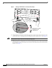
EMI
gasket
EMI
gasket
63585
Insert module
between slot guides