


17
Catalyst 6500 Series Switch and Cisco 7600 Series Router CMM Installation and Verification Note
78-14107-07
Installing and Removing the CMM
To remove a module from the chassis, perform these steps:
Step 1 Disconnect any network interface cables that are attached to the module.
Step 2 Verify that the captive installation screws on all of the modules in the chassis are tight.
This step assures that the space that is created by the removed module is maintained.
Note If the captive installation screws are loose, the electromagnetic interference (EMI) gaskets on
the installed modules will push the modules toward the open slot, reducing the opening size and
making it difficult to install the replacement module.
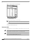
Step 3 Loosen the two captive installation screws on the module.
Step 4 Depending on the orientation of the slots in the chassis (horizontal or vertical), perform one of the
following sets of substeps:
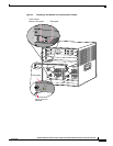
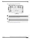
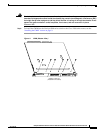
Horizontal slots
a. Place your thumbs on the left and right ejector levers, and simultaneously rotate the levers outward
to unseat the module from the backplane connector.
b. Grasp the front edge of the module, and slide the module part of the way out of the slot. Place your
other hand under the module to support the weight of the module. Do not touch the module
circuitry.
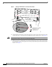
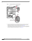
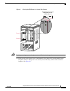
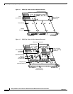
Vertical slots
a. Place your thumbs on the ejector levers that are located at the top and bottom of the module, and
simultaneously rotate the levers outward to unseat the module from the backplane connector.
b. Grasp the edges of the module, and slide the module straight out of the slot. Do not touch the
module circuitry.
Step 5 Place the module on an antistatic mat or antistatic foam, or immediately reinstall it in another slot.
Step 6 If the slot from which you removed the module is to remain empty, install a module filler plate to keep
dust out of the chassis and to maintain proper airflow through the chassis.
Warning
Blank faceplates and cover panels serve three important functions: they prevent exposure to
hazardous voltages and currents inside the chassis; they contain electromagnetic interference (EMI)
that might disrupt other equipment; and they direct the flow of cooling air through the chassis. Do not
operate the system unless all cards, faceplates, front covers, and rear covers are in place.
Statement 1029