


— 2 —
ENGLISH
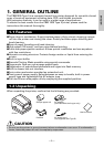
1. GENERAL OUTLINE ............................................................................. 9
1.1 Features ..................................................................................................... 9
1.2 Unpacking..................................................................................................9
2. BASIC SPECIFICATIONS .................................................................... 10
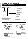
2.1 Model Classification ............................................................................... 10
2.2 Outer Appearance and Component Parts ............................................10
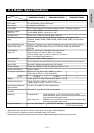
2.3 Basic Specifications ................................................................................11
2.4 Print Paper Specifications and Print Position ...................................... 12
2.5 Sensor Position and Cutter Position ..................................................... 13
3. OPERATION ........................................................................................ 14
3.1 Connecting the AC Adapter and AC Power Cord ................................ 14
3.2 Connecting Interface Cables ..................................................................14
3.3 Connecting the Drawer Kick-Out Connector ........................................15
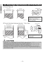
3.4 Setting/Replacing Paper Rolls ...............................................................16
3.5 Adjusting the Paper Near-End Sensor ..................................................16
3.6 Using 58 mm Wide Paper Rolls.............................................................17
3.7 Removing Jammed Paper .....................................................................17
3.8 Cleaning the Print Head .........................................................................17
3.9 Operation Panel and Error Indication ...................................................18
3.10 Self-printing...........................................................................................20
3.11 Hexadecimal Dump ..............................................................................20
3.12 Printer Buffer .........................................................................................21
3.13 Device ID ................................................................................................21
4. SETTING DIP SWITCHES ................................................................... 22
4.1 Location of DIP Switches .......................................................................22
4.2 Table for Setting DIP Switches ..............................................................22
5. MAINTENANCE AND SERVICE ......................................................... 24
APPENDIX 1. OUTLINE DRAWING .......................................................... i
APPENDIX 2. BLOCK DIAGRAM .............................................................. i
APPENDIX 3. IDENTIFICATION OF SEND STATUS ............................... ii
APPENDIX 4. PARALLEL INTERFACE .................................................... iii
APPENDIX 5. SERIAL INTERFACE .......................................................... v
APPENDIX 6. CONTROL COMMAND ................................................... vii
THE TABLE OF CONTENTS