


PPU-231 User’s Manual
13
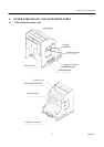
CITIZEN
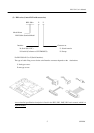
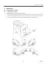
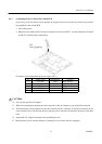
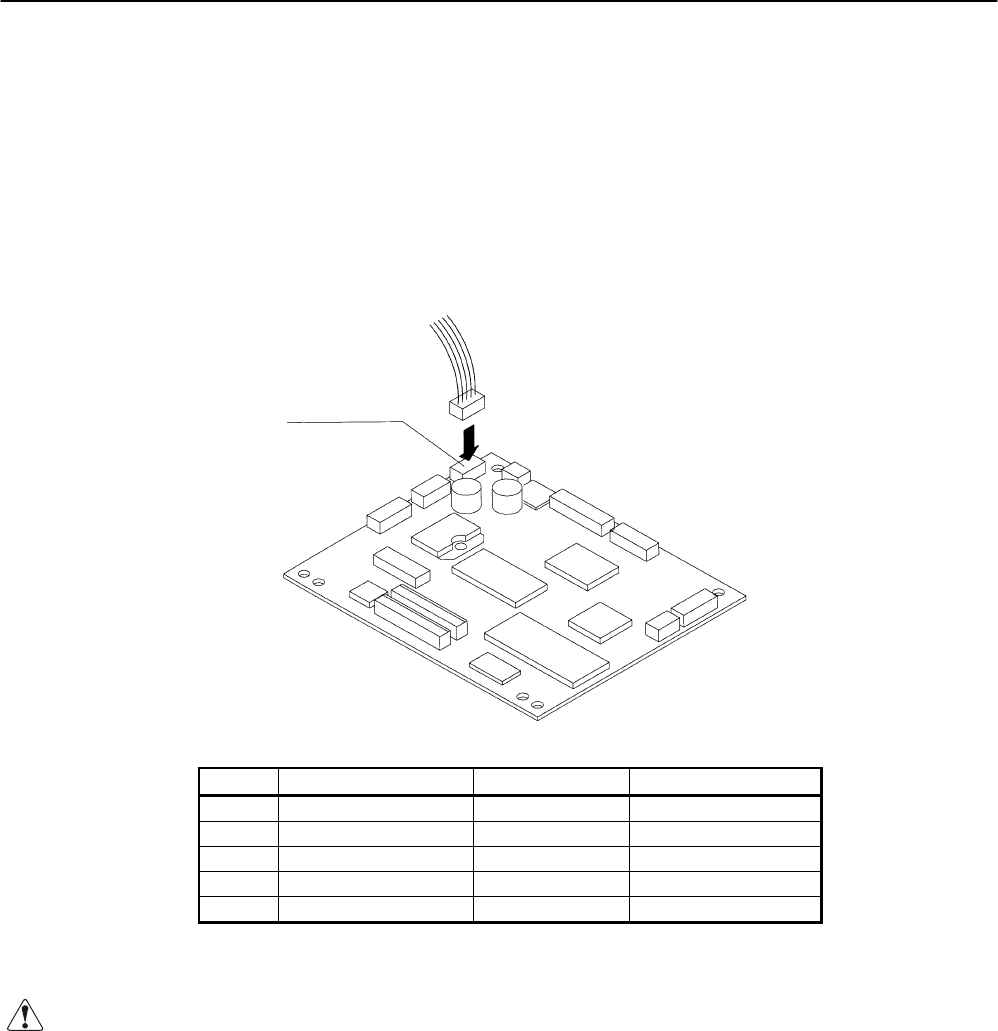
4.1.2 Connecting a Power Cable to the Control PCB
If you wish, you do not need to use an optional AC adapter, instead you can directly connect a power cable
(not supplied) to the control PCB.
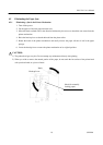
1. Turn off the power.
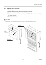
2. Plug the power cable into the CN1 power connector of the control PCB. See the table below for detail
on the CN1 connector pin configurations.
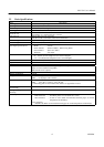
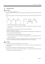
[Connector’s pin configuration for power supply (CN1)]
No. Signal Name Input/Output Function
1 +24V DC Input
Input Voltage
2 +24V DC Input Input Voltage
3 P-GND — GND
4 P-GND — GND
5 P-GND — GND
Connector used: 5267-05A-X (Molex)
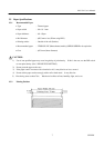
CAUTION:
4) Use only the specified AC adapter.
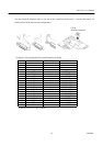
5) When disconnecting/reconnecting the cable connector of the AC adapter, be sure to hold the connector.
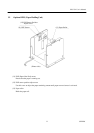
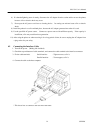
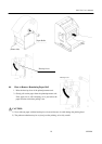
6) Several holes have been prepared on the unit so that the power connector or interface connector can be
easily attached. Never use the same hole for both the power connector and interface connector at the same
time.
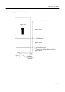
4) Separate the AC adapter from other noise-generating devices.
5) Pulling the AC power cord may damage it, resulting in a fire, electric shock, or snapping.
CN1
Power Connector