


CBM-230/231 User’s Manual
26
CITIZEN
8. DRAWER KICK CONNECTOR
8.1 Specifications
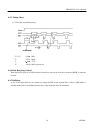
(1) Drawer kick drive signal
The pulses specified by ESC p are output. The state of the switch(+) can be known through the pin 34 of the interface
connector when parallel interface is used, and through the ESC u command when the serial interface is used.
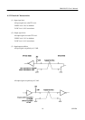
(2) Electrical characteristics
1) Drive voltage : DC 24 V
2) Drive current : 0.8 A at maximum(should be within 510 ms)
3) Switch signal : Signal level "L" = 0 to 0.5 V
"H" = 3 to 5 V
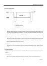
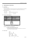
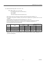
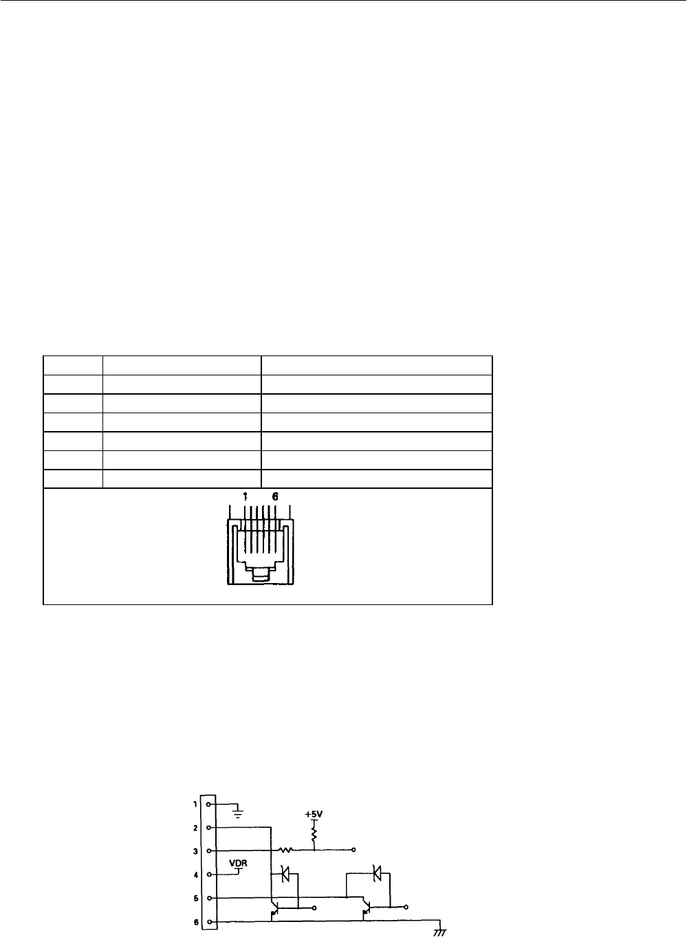
8.2 Connector's Pin Configuration
No. Signal Name Function
1 FG Frame ground
2 DRAWER 1 Drawer 1 drive signal
3 DRSW Drawer switch input
4 VDR Drawer driving power
5 DRAWER 2 Drawer 2 drive signal
6 GND Common ground on the circuits
Connector used : TM5RJ3-66(HIROSE)
Applicable connector : Equivalent to TM3P-66P(HIROSE)
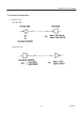
[Cautions] 1) No output is allowed during printing.
2) The drawers 1 and 2 cannot be driven at the same time.
3) A solenoid for the drawer should be of 36Ω or more.
(See to it that an output current will not exceed 0.8 A. Be careful not to use a drawer with a
current over 0.8A to avoid damage to the printer.)
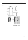
8.3 Drive Circuit