


CBM-230/231 User’s Manual
CITIZEN
CONTENTS
1. GENERAL DESCRIPTION ...............................................................................................................................1
1.1 Features............................................................................................................................................ 1
1.2 Precautions for Installation ............................................................................................................... 1
2. BASIC SPECIFICATIONS.................................................................................................................................2
2.1 Model Classification......................................................................................................................... 2
2.2 Specifications List ............................................................................................................................ 2
2.2 Specifications List ............................................................................................................................ 3
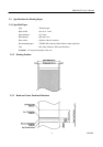
2.3 Specifications for Printing Paper....................................................................................................... 4
2.3.1 Specified Paper......................................................................................................................... 4
2.3.2 Printing Position ....................................................................................................................... 4
2.3.3 Head and Cutter Positional Relations ........................................................................................ 4
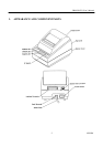
3. APPEARANCE AND COMPONENT PARTS .................................................................................................5
4. OPERATION........................................................................................................................................................6
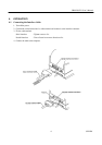
4.1 Connecting the Interface Cable ......................................................................................................... 6
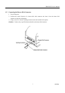
4.2 Connecting the Drawer Kick Connector............................................................................................ 6
4.2 Connecting the Drawer Kick Connector............................................................................................ 7
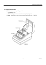
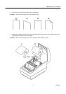
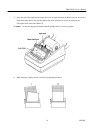
4.3 Inserting the Paper Roll .................................................................................................................... 8
4.4 Operation Panel.............................................................................................................................. 12
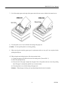
4.5 Opening the Auto Cutter(CBM-231)............................................................................................... 13
5. SETTING OF DIP SWITCHES .......................................................................................................................14
6. PARALLEL INTERFACE................................................................................................................................16
6.1 Specifications ................................................................................................................................. 16
6.2 Connector's Pin Configuration ........................................................................................................ 16
6.3 Input / Output Signals ..................................................................................................................... 17
6.3.1 Input / Output Signals ............................................................................................................. 17
6.3.2 Electrical Characteristics......................................................................................................... 18
6.3.3 Timing Chart .......................................................................................................................... 19
6.3.4 Data Receiving Control........................................................................................................... 19
6.3.5 Buffering ................................................................................................................................ 19
7. SERIAL INTERFACE ......................................................................................................................................20
7.1 Specifications ................................................................................................................................. 20
7.2 Connector's Pin Configuration ........................................................................................................ 21
7.3 Input / Output Signals ..................................................................................................................... 22
7.3.1 Input / Output Signals ............................................................................................................. 22
7.3.2 Data Configuration.................................................................................................................. 23
7.3.3 Error Detection ....................................................................................................................... 23
7.3.4 Data Receiving Control........................................................................................................... 24