


CONTENTS
1. OUTLINE..........................................................................................................................................................1
1.1 Features...................................................................................................................................................................1
1.2 Unpacking...............................................................................................................................................................1
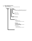
2. BASIC SPECIFICATIONS ...............................................................................................................................2
2.1 Model Classifications.............................................................................................................................................2
2.2 Basic Specifications................................................................................................................................................3
2.3 Paper Specifications ...............................................................................................................................................4
2.3.1 Recommended Paper...................................................................................................................................4
2.3.2 Printing Position..........................................................................................................................................4
2.3.3 Cutter Layout ..............................................................................................................................................4
3. OUTER APPEARANCE AND COMPONENT PARTS.....................................................................................5
3.1 iDP-3550.................................................................................................................................................................5
3.2 iDP-3551.................................................................................................................................................................6
4. OPERATION....................................................................................................................................................8
4.1 Detaching/Attaching the Printer Cover ..................................................................................................................8
4.2 Connecting the Interface Cable ..............................................................................................................................8
4.3 Connecting the Drawer Kick-Out Connector.........................................................................................................9
4.4 Opening/Closing the Auto Cutter (iDP-3551)........................................................................................................9
4.5 Setting the Ribbon Cassette..................................................................................................................................10
4.6 Inserting the Paper................................................................................................................................................11
4.7 Attaching the Rear Cover.....................................................................................................................................13
4.8 How to Remove Remaining Paper Roll ...............................................................................................................13
4.9 Removing Paper Jam............................................................................................................................................13
4.10 Unlocking the Cutter (iDP-3551).........................................................................................................................14
4.11 Operation Panel and Display of Error ..................................................................................................................15
5. DIP SWITCH SETTING................................................................................................................................. 17
5.1 Location of DIP Switch........................................................................................................................................17
5.2 DIP Switches Setting............................................................................................................................................18
6. PRESET JUMPER SETTING..........................................................................................................................20
6.1 Location of Preset Jumper....................................................................................................................................20
6.2 Preset Jumper Table .............................................................................................................................................20
7. MODE SETTING METHOD .......................................................................................................................... 21
8. INPUT BUFFER BACKUP FUNCTION ........................................................................................................ 22
8.1 Buffer Size............................................................................................................................................................22
8.2 Input Buffer Backup.............................................................................................................................................22
8.3 Clearing the Input Buffer......................................................................................................................................22
9. PARALLEL INTERFACE .............................................................................................................................. 23
9.1 Specifications .......................................................................................................................................................23
9.2 Connector's Pin Configuration .............................................................................................................................23
9.3 Input and Output Signals......................................................................................................................................24
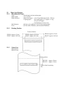
9.3.1 Input and Output Signals...........................................................................................................................24
9.3.2 Electrical Characteristics...........................................................................................................................25
9.3.3 Timing Chart.............................................................................................................................................26